THAT — The Analog Thing · Volume 6
THE Analog Thing — Volume 6 — Expansion & hybrid
Scaling compute resources across multiple THATs, daisy-chain control bus, and bridging to digital systems via the HYBRID port
6.1 About this Volume
Volume 6 addresses the two principal ways to extend what a single THAT can accomplish: adding more analog computing muscle by linking multiple units through the MASTER OUT / MINION IN ribbon cable, and bridging the analog domain to digital systems through the HYBRID port on the rear panel. These capabilities existed from THAT’s earliest prototypes — newsletter #1 (September 2021) already reported excitement about putting the newly added HYBRID port to work — and have matured into the foundation of Anabrid’s broader product ecosystem.
The reader is assumed to be comfortable with single-unit operation, element inventory, and machine-unit scaling from earlier volumes. Vol 2 covers the hardware architecture and the ±10 V machine-unit convention (derived from ±12 V internal rails). Vol 3 covers the computing-element inventory (5 integrators, 4 summers, 4 inverters, 2 multipliers, 2 comparators, 8 coefficient potentiometers) and the patching system. Vol 4 covers programming methodology including time-scaling. Readers arriving here without that background should review those volumes first.
Scope of verified claims — All element counts, connector pinouts, and voltage values in this volume are derived from the THAT v1.3 schematics (Analog Paradigm, 03.2022), the First Steps v2.0 manual (anabrid GmbH, 2023), the official wiki at the-analog-thing.org, and the sixteen newsletters (2021–2023). Where the source documents are silent on a detail, this text says so explicitly rather than speculating.
6.2 The HYBRID Connector
6.2.1 Physical Description
The rear panel of THAT carries four connectors relevant to expansion and hybrid use:
Table 1 — The rear panel of THAT carries four connectors relevant to expansion and hybrid use
| Designator | Physical form | Purpose |
|---|---|---|
| USB-C IN | USB-C receptacle | 5 V power input (data pins unused) |
| MINION IN | 10-pin IDC ribbon header | Receives control bus from an upstream MASTER |
| MASTER OUT | 10-pin IDC ribbon header | Drives the control bus to a downstream MINION |
| HYBRID | 20-pin IDC ribbon header | Analog signal outputs + digital control I/O |
| RCA × 4 | Phono jacks (X, Y, Z, U) | Attenuated ±1 V analog outputs |
| RCA TRIGGER | Phono jack | 5 V TTL trigger output for oscilloscope sync |
The HYBRID connector is the widest header on the rear panel and is the primary interface for analog-digital hybrid system development.
6.2.2 HYBRID Port Electrical Characteristics
The HYBRID port serves two distinct functions simultaneously: it exposes the four patch-panel output signals (corresponding to whichever signals are plugged into the X, Y, Z, and U output jacks on the front panel) and it accepts digital control inputs from an external microcontroller.
Signal conditioning on the analog outputs. The four patch-panel signals nominally swing ±10 V (the THAT machine unit). The HYBRID port attenuates and level-shifts these before presenting them at the header pins, as stated explicitly in the First Steps manual: “Outputs on the HYBRID Port are attenuated and shifted to 0 V to 3.3 V to facilitate analog/digital conversion.” This places the signal comfortably within the ADC input range of 3.3 V CMOS microcontrollers without external level shifting. The wiki confirms: “The hybrid port logic levels are CMOS, i.e. compatible with Raspberry Pi, modern Arduinos, ESPs, Teensys, etc.”
The conditioning formula for each analog output channel is:
V_hyb = (V_patch / 20) × 3.3 V + 1.65 VThat is, −10 V maps to approximately 0 V at the HYBRID header and +10 V maps to approximately 3.3 V, with mid-scale (0 V on the patch field) mapping to approximately 1.65 V. Exact component values are set by the resistor divider network visible in THAT Base schematic sheet 5 (THAT-Base_v1.3_05.png), which feeds four TL074H op-amp stages labelled IC31a–d. Those op-amp outputs are labelled HYB-X, HYB-Y, HYB-Z, and HYB-U respectively.
Digital control inputs. Dedicated pins on the HYBRID header carry the same mode-control signals as the MASTER/MINION bus — specifically ModeIC, ModeOP, and an Enable line — allowing an external microcontroller to assert IC and OP transitions without the user touching the front-panel mode selector. Logic levels are 3.3 V CMOS.
6.2.3 HYBRID Port Pinout
The table below is derived from the wiki’s hybrid-computing article and the THAT Base v1.3 schematic, cross-referenced against the Arduino Mega 2650 example documented in newsletter #2 and the wiki. The specific pin assignments are reconstructed from the Anabrid wiki and community sources and are not directly confirmed from the V1.3 schematic sheets; consult THAT_hybrid_port_desc.pdf on the official wiki for the authoritative pinout. Odd-numbered pins not listed below are reserved or NC in the v1.3 design.
Table 2 — HYBRID Port Pinout
| Pin | Signal | Direction | Notes |
|---|---|---|---|
| 2 | HYB-X | Output | Analog X, 0–3.3 V |
| 4 | HYB-Y | Output | Analog Y, 0–3.3 V |
| 6 | HYB-Z | Output | Analog Z, 0–3.3 V |
| 8 | HYB-U | Output | Analog U, 0–3.3 V |
| 9 | GND | — | Signal ground |
| 10 | GND | — | Signal ground |
| 13 | Enable | Input | Active-high; enables hybrid control |
| 14 | MOP (ModeOP) | Input | Active-high; sets OP mode |
| 16 | MIC (ModeIC) | Input | Active-high; sets IC mode |
Note — The HYBRID connector IC (IC33 in the schematic, a 74LVC245 octal bus transceiver) handles direction control and provides additional ESD protection. The schematic also shows a SNOFF signal and a ModeOFF line on the same header. The exact function of SNOFF is not described in the public documentation reviewed for this volume.
6.2.4 ADC Requirements
The 0–3.3 V, single-ended, DC-coupled signal at the HYBRID header is ready for direct connection to any 3.3 V ADC. Resolution requirements depend on the application:
Table 3 — The 0–3.3 V, single-ended, DC-coupled signal at the HYBRID header is ready for direct connection to any 3.3 V ADC. Resolution requirements depend on the application
| Use case | Min ADC resolution | Effective LSB at ±10 V |
|---|---|---|
| Qualitative data logging | 8-bit | ≈78 mV |
| Engineering data logging | 10-bit | ≈19.5 mV |
| Calibration / precision work | 12-bit | ≈4.9 mV |
| Research-grade capture | 16-bit | ≈0.3 mV |
The LUCIDAC hybrid controller uses external 16-bit ADCs for research-grade capture. For educational work with THAT alone, the 10-bit SAR ADC built into most Arduino and similar microcontrollers is adequate for observing waveform shapes, measuring equilibrium values, and cross-checking oscilloscope readings.
Tip — THAT draws approximately 300 mA from its USB-C power supply. Never power THAT from the 5 V rail of an Arduino or similar microcontroller; the onboard regulator cannot supply enough current, leading to brown-out and incorrect operation. Always use a dedicated USB power adapter for THAT and connect only signal and ground lines between the two boards.
6.2.5 Schematic View — HYBRID Signal Chain
Patch-panel output jack (±10 V)
          │
          ▼
  Front PCB via-through  ──────────────────────────────────────────────────────┐
                                                                               │
  Base PCB, sheet 5:                                                           │
   R124/R126  (voltage divider, sets gain < 1)                                 │
          │                                                                    │
          ▼                                                                    │
   IC31a–d (TL074H op-amp, level-shift & buffer)                              │
          │          ±12 V supply rails                                        │
          ▼                                                                    │
   HYB-X/Y/Z/U  ──► IC33 (74LVC245 transceiver) ──► HYBRID header pin 2/4/6/8│
                       │                                                       │
                  ModeIC / ModeOP / Enable pins ◄── external µC               │
                                                                               │
  R116 / R117 / R118 / R119 (470 Ω series resistors)                          │
          │                                                                    │
          ▼                                                                    │
   RCA jacks X/Y/Z/U   (±1 V, audio-compatible)  ◄────────────────────────────┘
Note: The two output paths (HYBRID header and RCA jacks) both originate from the same front-panel output jacks. The resistor values shown for the RCA path (470 Ω) are readable in THAT-Base_v1.3_05.png; the conditioning op-amp designators are IC31a–d.
6.3 The MASTER OUT / MINION IN Control Bus
6.3.1 Topology and Naming
THAT uses the terms MASTER and MINION to describe the roles of units in a daisy-chain. The unit furthest upstream — typically leftmost on the bench — drives the bus and is the MASTER. Every other unit in the chain is a MINION and must have its front-panel Mode Selector set to the MINION position. There is no physical limit to chain length stated in the official documentation; the First Steps manual explicitly says “There is no limit to the number of THATs that can be linked in a minion chain.”
Newsletter #4 documented the first public use of a two-THAT master/minion chain, with students at Universität Ulm implementing a rotating Rössler attractor across both units. Newsletter #12 confirms that the included ribbon cable ships with every THAT specifically for this purpose.
6.3.2 MASTER OUT / MINION IN Electrical Interface
Both MASTER OUT and MINION IN use 10-pin IDC (ribbon cable) headers and are connected with the flat ribbon cable included in every THAT box. The pinout is derived from the wiki’s Master and Minion documentation pages:
Note — The pin assignments in the MASTER OUT and MINION IN tables below are reconstructed from the Anabrid wiki and community documentation; they are not directly confirmed from the V1.3 schematic sheets at the resolution available. Treat them as wiki-derived/unverified and consult
THAT_hybrid_port_desc.pdfand the official wiki for the authoritative map.
MASTER OUT pinout (sourced from the-analog-thing.org/wiki/Master):
Table 4 — MASTER OUT pinout (sourced from the-analog-thing.org/wiki/Master):
| Pin | Signal | Notes |
|---|---|---|
| 1, 2, 3 | GND | Signal ground |
| 4 | Potset | Coefficient potentiometer set strobe |
| 5 | Enable | Bus enable |
| 6 | ModeIC | Asserts IC on all downstream units |
| 7 | NC | No connection |
| 8 | ModeOP | Asserts OP on all downstream units |
| 9, 10 | Vcc | Power to bus logic |
MINION IN pinout (sourced from the-analog-thing.org/wiki/Minion):
Table 5 — MINION IN pinout (sourced from the-analog-thing.org/wiki/Minion):
| Pin | Signal | Notes |
|---|---|---|
| 1, 2 | GND | Signal ground |
| 3 | MINION | Mode identification signal |
| 4 | Potset | Coefficient potentiometer set strobe |
| 5 | Enable | Bus enable |
| 6 | ModeIC | IC mode assertion input |
| 7 | NC | No connection |
| 8 | ModeOP | OP mode assertion input |
| 9, 10 | SWOFF | Switch-off signal |
The physical connector viewed in schematic THAT-Base_v1.3_01.png (upper left region) shows the ribbon cable header labeled “MinionIn” connected to a 74LVC245S (IC33) bus transceiver driving the mode-control latches, consistent with the pin descriptions above.
6.3.3 Control Bus Behavior
When a unit is set to MINION mode, the front-panel Mode Selector is overridden by the signals arriving at the MINION IN header. The MASTER unit’s Mode Selector governs the entire chain:
- OP mode on the MASTER simultaneously starts integration on all MINION units.
- IC mode on the MASTER simultaneously loads initial conditions on all units.
- HALT on the MASTER halts integration on all units.
- REP and REPF on the MASTER drive the entire chain through repetitive IC → OP cycles in synchrony.
- COEFF mode — each unit’s eight coefficient potentiometers remain independently settable even in a chain. The wiki notes: “In the COEFFICIENT mode, the values for the eight coefficients on any device can be setup separately while IC/OP/HALT/REP/REPF modes are controlled only from the MASTER.”
- The OP-Time potentiometer and the Panel Meter on the MASTER remain in control of timing; MINION units’ own pots are bypassed for timing purposes.
6.3.4 Daisy-Chain Topology Diagram
<svg xmlns="http://www.w3.org/2000/svg" viewBox="0 0 780 200" font-family="monospace" font-size="13">
  <!-- MASTER unit -->
  <rect x="10" y="60" width="160" height="80" rx="6" fill="#e8f4e8" stroke="#2a6e2a" stroke-width="2"/>
  <text x="90" y="88" text-anchor="middle" font-weight="bold" fill="#2a6e2a">THAT #1</text>
  <text x="90" y="106" text-anchor="middle" fill="#2a6e2a">MASTER</text>
  <text x="90" y="122" text-anchor="middle" font-size="11" fill="#555">Mode Selector active</text>
  <!-- MASTER OUT label -->
  <text x="170" y="98" font-size="11" fill="#333">MASTER</text>
  <text x="170" y="112" font-size="11" fill="#333">OUT ►</text>

  <!-- Ribbon cable 1→2 -->
  <rect x="230" y="86" width="80" height="28" rx="4" fill="#f0e8c0" stroke="#8a7a20" stroke-width="1.5"/>
  <text x="270" y="105" text-anchor="middle" font-size="11" fill="#5a4a00">ribbon cable</text>

  <!-- MINION 1 unit -->
  <rect x="310" y="60" width="160" height="80" rx="6" fill="#e8eef8" stroke="#1a3e8a" stroke-width="2"/>
  <text x="390" y="88" text-anchor="middle" font-weight="bold" fill="#1a3e8a">THAT #2</text>
  <text x="390" y="106" text-anchor="middle" fill="#1a3e8a">MINION</text>
  <text x="390" y="122" text-anchor="middle" font-size="11" fill="#555">Mode Selector → MINION</text>
  <text x="314" y="98" font-size="11" fill="#333">◄ MINION</text>
  <text x="314" y="112" font-size="11" fill="#333">IN</text>
  <text x="470" y="98" font-size="11" fill="#333">MASTER</text>
  <text x="470" y="112" font-size="11" fill="#333">OUT ►</text>

  <!-- Ribbon cable 2→3 -->
  <rect x="530" y="86" width="80" height="28" rx="4" fill="#f0e8c0" stroke="#8a7a20" stroke-width="1.5"/>
  <text x="570" y="105" text-anchor="middle" font-size="11" fill="#5a4a00">ribbon cable</text>

  <!-- MINION 2 unit -->
  <rect x="610" y="60" width="160" height="80" rx="6" fill="#e8eef8" stroke="#1a3e8a" stroke-width="2"/>
  <text x="690" y="88" text-anchor="middle" font-weight="bold" fill="#1a3e8a">THAT #3</text>
  <text x="690" y="106" text-anchor="middle" fill="#1a3e8a">MINION</text>
  <text x="690" y="122" text-anchor="middle" font-size="11" fill="#555">Mode Selector → MINION</text>
  <text x="614" y="98" font-size="11" fill="#333">◄ MINION</text>
  <text x="614" y="112" font-size="11" fill="#333">IN</text>

  <!-- Control signal annotation -->
  <line x1="90" y1="40" x2="690" y2="40" stroke="#c00" stroke-width="1.5" stroke-dasharray="5,3"/>
  <polygon points="685,36 695,40 685,44" fill="#c00"/>
  <text x="380" y="32" text-anchor="middle" font-size="11" fill="#c00">OP / IC / HALT / REP control propagates left → right</text>

  <!-- Signal sharing annotation -->
  <text x="90" y="175" text-anchor="middle" font-size="11" fill="#333">Patch signals shared</text>
  <text x="90" y="188" text-anchor="middle" font-size="11" fill="#333">via banana cables</text>
  <line x1="170" y1="182" x2="310" y2="182" stroke="#888" stroke-width="1" stroke-dasharray="4,2"/>
  <line x1="470" y1="182" x2="610" y2="182" stroke="#888" stroke-width="1" stroke-dasharray="4,2"/>
  <text x="390" y="175" text-anchor="middle" font-size="11" fill="#333">Patch signals shared</text>
  <text x="390" y="188" text-anchor="middle" font-size="11" fill="#333">via banana cables</text>
</svg>
Note — The ribbon cable connects MASTER OUT on unit N to MINION IN on unit N+1. Signal sharing between units — feeding the output of an integrator on THAT #1 into the input of a summer on THAT #2, for example — requires ordinary banana-plug patch cables across the front panels. The ribbon cable carries only mode-control signals, not analog computing signals.
6.4 Multi-Unit Programs — Scaling a Large Problem Across Stacked Units
6.4.1 When One THAT Is Not Enough
A single THAT provides (verified from the First Steps v2.0 manual, section 7, and the v1.3 front-panel schematic):
Table 6 — A single THAT provides (verified from the First Steps v2.0 manual, section 7, and the v1.3 front-panel schematic)
| Element | Count |
|---|---|
| Integrators | 5 (each with 5 inputs, 2 of which are ×10 weighted) |
| Summers | 4 (each with 7 inputs, 3 of which are ×10 weighted) |
| Multipliers (4-quadrant) | 2 |
| Comparators | 2 |
| Coefficient potentiometers | 8 |
| Inverters | 4 (two pairs; plus the implicit sign inversion of integrators and summers) |
| Resistor networks (XIR) | 2 |
| ±1 machine unit sources | 2 banks |
| Diodes / Zener diodes | Available on front panel |
Many differential equations of engineering interest — fourth- and higher-order systems, coupled PDEs discretised by method of lines, large predator/prey webs, full Lorenz families — exhaust those resources. A two-THAT chain doubles the element budget; a three-THAT chain triples it; no ceiling is documented.
6.4.2 Partitioning Strategy
Effective partitioning follows the structure of the differential equation system rather than arbitrary load-balancing:
-
Assign state variables to units. Group state variables whose derivatives share many common sub-expressions onto the same unit to minimise cross-unit banana-cable runs. Cross-unit wiring does not degrade electrical performance (all outputs are low-impedance, ≤100 Ω) but increases physical complexity and error risk.
-
Place integrators first. Each integrator output is a state variable. Identify how many integrators the full system requires and distribute them across units before placing summers and multipliers.
-
Keep nonlinear elements close to their consumers. Multiplier outputs and comparator outputs that feed only one or two integrators should reside on the same unit as those integrators.
-
Use only one coefficient potentiometer per coefficient, across all units. Coefficients shared between units must be set on one unit and patched across. Both units need not replicate the same pot setting.
-
Reserve the MASTER’s X/Y/Z/U jacks for the most important outputs. Those jacks connect to the rear RCA and HYBRID ports. MINION units’ output jacks are front-panel-only and must be patched to the MASTER’s output jacks if they are to be observed via oscilloscope or DAQ.
6.4.3 Scaling Example: Two-THAT Rössler Attractor
The Rössler system requires three integrators and uses multipliers and summers in a moderately coupled way. A typical two-unit partition documented in newsletter #4:
┌─────────────────────────────────────────────────┐
│  THAT #1 (MASTER)                               │
│  INT1: ẋ = −y − z                              │
│  INT2: ẏ = x + ay                               │
│  SUM1: forms (x + ay)                           │
│  COEFF pots: a, time-scale factor               │
│  Output jacks: X→x(t), Y→y(t)                  │
└─────────────────────────────────────────────────┘
         │ x(t), y(t) via banana cables ↓
┌─────────────────────────────────────────────────┐
│  THAT #2 (MINION, Mode Selector → MINION)       │
│  INT1: ż = b + z(x − c)                        │
│  MUL1: computes z·x                             │
│  SUM1: forms b + z(x−c)                         │
│  COEFF pots: b, c                               │
│  Output: z(t) patched back to THAT #1 INT1      │
└─────────────────────────────────────────────────┘
The closed feedback loop for z crosses the unit boundary via a single banana cable from THAT #2’s integrator output to one of THAT #1’s integrator inputs. Synchronous IC/OP cycling is handled automatically by the ribbon cable.
6.4.4 Resource Accounting Table for N-Unit Chains
Table 7 — Resource Accounting Table for N-Unit Chains
| Units | Integrators | Summers | Multipliers | Comparators | Coeff pots |
|---|---|---|---|---|---|
| 1 | 5 | 4 | 2 | 2 | 8 |
| 2 | 10 | 8 | 4 | 4 | 16 |
| 3 | 15 | 12 | 6 | 6 | 24 |
| 4 | 20 | 16 | 8 | 8 | 32 |
| N | 5N | 4N | 2N | 2N | 8N |
Tip — Time scaling must be consistent across all units in a chain. Because the ribbon cable distributes a single ModeOP / ModeIC pulse to all units simultaneously, there is no mechanism for running different units at different time scales within the same compute run. Apply a single, consistent time-scale factor throughout the partition.
6.4.5 Cross-Unit Signal Wiring Guidance
Cross-unit analog signals travel through standard 2 mm banana-plug patch cables. There is no fixed limit on the number of such cables that can cross unit boundaries. Practical constraints:
- Each output jack can drive multiple inputs (stacking banana plugs is supported).
- Each input jack accepts only one signal; use a summer if a cross-unit signal must be added to a local signal.
- Cable lengths of 30 cm or more may pick up interference in electrically noisy environments; shielded 2 mm banana cables are available from specialist suppliers.
- Label cross-unit cables with colour-coded sleeves or tags before debugging begins — the patch diagram can become difficult to trace once a dozen cables span two or three THAT front panels.
6.5 Digital Interfacing and Data Logging
6.5.1 Interfacing Architecture Overview
<svg xmlns="http://www.w3.org/2000/svg" viewBox="0 0 740 340" font-family="sans-serif" font-size="12">
  <!-- THAT box -->
  <rect x="10" y="80" width="220" height="180" rx="8" fill="#e8f4e8" stroke="#2a6e2a" stroke-width="2"/>
  <text x="120" y="105" text-anchor="middle" font-size="14" font-weight="bold" fill="#2a6e2a">THAT</text>
  <text x="120" y="122" text-anchor="middle" font-size="11" fill="#555">Analog compute core</text>
  <text x="120" y="140" text-anchor="middle" font-size="11" fill="#555">±10 V machine unit</text>

  <!-- Outputs inside THAT -->
  <rect x="25" y="155" width="90" height="20" rx="3" fill="#c8e8c8" stroke="#2a6e2a"/>
  <text x="70" y="169" text-anchor="middle" font-size="10" fill="#2a6e2a">X/Y/Z/U jacks</text>
  <rect x="25" y="182" width="90" height="20" rx="3" fill="#c8e8c8" stroke="#2a6e2a"/>
  <text x="70" y="196" text-anchor="middle" font-size="10" fill="#2a6e2a">HYBRID port</text>
  <rect x="25" y="209" width="90" height="20" rx="3" fill="#c8e8c8" stroke="#2a6e2a"/>
  <text x="70" y="223" text-anchor="middle" font-size="10" fill="#2a6e2a">RCA X/Y/Z/U</text>
  <rect x="25" y="236" width="90" height="20" rx="3" fill="#c8e8c8" stroke="#2a6e2a"/>
  <text x="70" y="250" text-anchor="middle" font-size="10" fill="#2a6e2a">RCA TRIGGER</text>

  <!-- Arrows to right -->
  <!-- HYBRID arrow -->
  <line x1="230" y1="192" x2="310" y2="192" stroke="#1a6e8a" stroke-width="2"/>
  <polygon points="305,188 315,192 305,196" fill="#1a6e8a"/>
  <text x="270" y="185" text-anchor="middle" font-size="10" fill="#1a6e8a">0–3.3 V</text>
  <text x="270" y="208" text-anchor="middle" font-size="10" fill="#1a6e8a">CMOS ctrl</text>

  <!-- RCA arrow -->
  <line x1="230" y1="219" x2="310" y2="270" stroke="#8a4a1a" stroke-width="2"/>
  <polygon points="306,266 315,272 308,277" fill="#8a4a1a"/>
  <text x="265" y="255" text-anchor="middle" font-size="10" fill="#8a4a1a">±1 V</text>

  <!-- Microcontroller box -->
  <rect x="315" y="140" width="180" height="100" rx="8" fill="#e8eef8" stroke="#1a3e8a" stroke-width="2"/>
  <text x="405" y="165" text-anchor="middle" font-size="13" font-weight="bold" fill="#1a3e8a">µController</text>
  <text x="405" y="183" text-anchor="middle" font-size="11" fill="#555">Arduino / Teensy /</text>
  <text x="405" y="198" text-anchor="middle" font-size="11" fill="#555">Raspberry Pi / ESP32</text>
  <text x="405" y="216" text-anchor="middle" font-size="11" fill="#555">3.3 V CMOS I/O</text>
  <text x="405" y="231" text-anchor="middle" font-size="11" fill="#555">10–16 bit ADC</text>

  <!-- Audio interface box -->
  <rect x="315" y="250" width="180" height="70" rx="8" fill="#f8eecc" stroke="#8a6a1a" stroke-width="2"/>
  <text x="405" y="275" text-anchor="middle" font-size="13" font-weight="bold" fill="#8a6a1a">Audio Interface</text>
  <text x="405" y="292" text-anchor="middle" font-size="11" fill="#555">USB sound card</text>
  <text x="405" y="307" text-anchor="middle" font-size="11" fill="#555">Software oscilloscope</text>

  <!-- USB to PC -->
  <line x1="495" y1="192" x2="580" y2="192" stroke="#555" stroke-width="2"/>
  <polygon points="575,188 585,192 575,196" fill="#555"/>
  <text x="535" y="185" text-anchor="middle" font-size="10" fill="#555">USB / Serial</text>
  <text x="535" y="205" text-anchor="middle" font-size="10" fill="#555">Ethernet</text>

  <!-- PC box -->
  <rect x="585" y="140" width="140" height="100" rx="8" fill="#f0f0f0" stroke="#444" stroke-width="2"/>
  <text x="655" y="165" text-anchor="middle" font-size="13" font-weight="bold" fill="#333">Host PC</text>
  <text x="655" y="183" text-anchor="middle" font-size="11" fill="#555">Python / C++</text>
  <text x="655" y="198" text-anchor="middle" font-size="11" fill="#555">gnuplot / NumPy</text>
  <text x="655" y="216" text-anchor="middle" font-size="11" fill="#555">MATLAB / Julia</text>
  <text x="655" y="231" text-anchor="middle" font-size="11" fill="#555">Rust / Go clients</text>

  <!-- Audio to PC -->
  <line x1="495" y1="285" x2="580" y2="230" stroke="#8a6a1a" stroke-width="1.5" stroke-dasharray="5,3"/>
  <polygon points="575,226 584,232 578,239" fill="#8a6a1a"/>
  <text x="543" y="262" text-anchor="middle" font-size="10" fill="#8a6a1a">USB audio</text>

  <!-- Mode control arrow (reverse) -->
  <line x1="315" y1="172" x2="230" y2="172" stroke="#c00" stroke-width="1.5" stroke-dasharray="4,2"/>
  <polygon points="235,168 225,172 235,176" fill="#c00"/>
  <text x="272" y="165" text-anchor="middle" font-size="10" fill="#c00">ModeIC / ModeOP</text>
  <text x="272" y="177" text-anchor="middle" font-size="10" fill="#c00">Enable (CMOS in)</text>

  <!-- Legend -->
  <rect x="10" y="285" width="220" height="45" rx="4" fill="#fafafa" stroke="#aaa"/>
  <text x="120" y="302" text-anchor="middle" font-size="11" font-weight="bold" fill="#333">Signal paths</text>
  <line x1="20" y1="315" x2="50" y2="315" stroke="#1a6e8a" stroke-width="2"/>
  <text x="55" y="319" font-size="10" fill="#333">HYBRID (0–3.3 V analog + CMOS ctrl)</text>
  <line x1="20" y1="330" x2="50" y2="330" stroke="#8a4a1a" stroke-width="2"/>
  <text x="55" y="334" font-size="10" fill="#333">RCA (±1 V analog, audio-compatible)</text>
</svg>
6.5.2 Output Path Comparison
THAT provides three distinct analog output paths, each suited to different external measurement equipment:
Table 8 — THAT provides three distinct analog output paths, each suited to different external measurement equipment
| Path | Connector | Voltage range | Impedance | Best use |
|---|---|---|---|---|
| Front panel output jacks | 2 mm banana | ±10 V | Low (output amp) | Banana-to-BNC adapters, benchtop scopes |
| RCA Out (X/Y/Z/U) | Phono jack | ±1 V | 560 Ω source | Audio interfaces, software oscilloscopes |
| HYBRID port (analog pins) | 20-pin IDC | 0–3.3 V | Set by IC31 op-amp | Microcontroller ADC, DAQ boards |
| RCA TRIGGER | Phono jack | 0/5 V TTL | — | Oscilloscope external trigger input |
The ±1 V RCA outputs are attenuated by ×10 from the machine unit (×470 Ω series resistors visible in THAT-Base_v1.3_05.png). The 0–3.3 V HYBRID outputs apply additional offset shifting. Both paths are DC-coupled and can represent slowly varying or static voltages.
Note — The First Steps manual (section 6.2) explicitly warns that audio interface inputs contain capacitors that filter out DC and low-frequency components, distorting waveforms. This makes the RCA path unsuitable for observing slowly evolving systems (long OP times, time-scaled populations, etc.) but adequate for oscillatory outputs above a few hertz. The HYBRID path is DC-coupled throughout and does not suffer this limitation.
6.5.3 Microcontroller Interface — Arduino Example
The wiki documents a working hybrid interface using an Arduino Mega 2650 with a custom piggy-back adapter board. The key software dependencies are the TimerThree and TimerFive libraries for precise IC/OP timing. The command set exposed by the firmware includes:
Table 9 — The wiki documents a working hybrid interface using an Arduino Mega 2650 with a custom piggy-back adapter board. The key software dependencies are the TimerThree and TimerFive libraries for precise IC/OP timing. The command set exposed by the firmware includes
| Command | Function |
|---|---|
enable / disable | Activate / deactivate hybrid control via the HYBRID port Enable pin |
ic | Assert ModeIC — loads initial conditions across all units |
op | Assert ModeOP — begins integration |
run | Execute a single IC → OP cycle and log ADC samples |
rep | Repetitive IC → OP cycling, streaming samples |
Example workflow for capturing a Hindmarsh–Rose neuron burst (documented in the wiki hybrid-computing article):
1. Patch the Hindmarsh–Rose program (requires ~ 3 integrators, 2 multipliers)
2. Connect THAT HYBRID port → piggy-back board → Arduino Mega
3. arduino> enable
4. arduino> ic          # loads initial conditions
5. arduino> run 50      # 50 ms OP run, logs X/Y/Z/U at Arduino ADC rate
6. Download sample array to host PC
7. Plot with gnuplot or Python/matplotlib
The ADC sampling rate of the Arduino Mega (with 10-bit SAR) is on the order of 10–50 kSa/s per channel at default clock settings, adequate for signals up to a few kilohertz — suitable for typical THAT REP-mode program speeds.
6.5.4 Data Logging via Oscilloscope
The most direct data capture path for one or two channels uses a USB oscilloscope connected to the front-panel output jacks via BNC-to-banana adapters (not included with THAT; available from electronics suppliers). Modern USB oscilloscopes provide sample rates from 100 MSa/s to 1 GSa/s and built-in export to CSV or binary format for post-processing.
For four-channel capture, the RCA Out jacks at the rear panel provide X, Y, Z, and U simultaneously. A four-channel USB oscilloscope or a four-channel audio interface (the latter limited to roughly 20 kHz bandwidth by audio-grade ADCs, per the First Steps manual’s warning) can capture all four simultaneously.
6.5.5 Data Logging via DAQ Board
USB and PCIe data-acquisition modules from National Instruments (NI USB-6001/6008/6009 family), Measurement Computing (MCC USB-1408FS), and Digilent (MCC 118) all accept ±10 V single-ended or differential inputs directly from the THAT front-panel output jacks, without the attenuation needed for audio interfaces. Typical specifications of suitable entry-level modules:
Table 10 — USB and PCIe data-acquisition modules from National Instruments (NI USB-6001/6008/6009 family), Measurement Computing (MCC USB-1408FS), and Digilent (MCC 118) all accept ±10 V single-ended or differential inputs directly from the THAT front-panel output jacks, without the attenuation needed for audio interfaces. Typical specifications of suitable entry-level modules
| Specification | Typical value |
|---|---|
| Input voltage range | ±10 V (matches THAT machine unit exactly) |
| Resolution | 12–16 bit |
| Max sample rate | 10–50 kSa/s (USB devices) |
| Channels | 4–8 |
| Software | Python (nidaqmx, mcculw), MATLAB, LabVIEW |
At ±10 V with 12-bit resolution the LSB is approximately 4.9 mV, which gives effective noise-limited precision of about two decimal places in machine units — consistent with the First Steps manual’s statement that THAT is “precise to about two positions after the decimal point, relative to its machine unit.”
6.5.6 The Hybrid Thing (Community Project)
Newsletter #10 (August 2022) mentioned THE HYBRID THING, described as “still a work in progress” at that time: a community-developed hybrid controller purpose-built for coupling to THAT. The newsletter did not supply electrical specifications; that project should be tracked via the THAT Facebook group and the associated GitHub repositories for current status. Similarly, Karsten Hansky’s controller (cited in newsletter #13) was documented with schematic and source code in a public GitHub repository, providing an alternative to the Arduino Mega approach.
6.6 The Anabrid Ecosystem
THAT is the entry point of Anabrid’s analog/hybrid computing product line. Two further products sit above it in capability and price, forming a coherent ecosystem.
6.6.1 Product Hierarchy
┌────────────────────────────────────────────────────────────────────────────┐
│  Anabrid ecosystem — capability tiers (as of 2023–2024)                   │
├─────────────────┬──────────────────────────────┬───────────────────────────┤
│  Product        │  Target                      │  Machine unit / I/O       │
├─────────────────┼──────────────────────────────┼───────────────────────────┤
│  THAT           │  Education, hobbyist         │  ±10 V; 2mm banana        │
│  (this volume)  │  First-time users            │  HYBRID IDC header        │
├─────────────────┼──────────────────────────────┼───────────────────────────┤
│  LUCIDAC        │  Research labs, universities │  ±2 V I/O (±1 V logical) │
│                 │  Low-latency real-time apps  │  MCX coaxial; RJ45 Eth.  │
├─────────────────┼──────────────────────────────┼───────────────────────────┤
│  REDAC          │  Industrial, aerospace,      │  Not publicly specified   │
│                 │  neuromorphic AI, HPC        │  at time of writing       │
└─────────────────┴──────────────────────────────┴───────────────────────────┘
6.6.2 LUCIDAC
LUCIDAC (“Low-power, Ultra-fast, Compact Integrated Digital-Analog Computer”) is described by Anabrid as “the world’s first reconfigurable discrete analog computer for low-latency, real-time lab applications.” Its architecture differs substantially from THAT’s fixed-wiring philosophy:
Table 11 — LUCIDAC ("Low-power, Ultra-fast, Compact Integrated Digital-Analog Computer") is described by Anabrid as "the world's first reconfigurable discrete analog computer for low-latency, real-time lab applications." Its architecture differs substantially from THAT's fixed-wiring philosophy
| Feature | THAT | LUCIDAC |
|---|---|---|
| Interconnect | Manual banana-plug patching | Reconfigurable 16 × 16 routing matrix |
| Coefficient setting | Manual potentiometers | Software-set digital potentiometers |
| Machine unit (external I/O) | ±10 V | ±2 V |
| ADC (built-in) | None | External 16-bit ADCs |
| Hybrid controller | External (Arduino etc.) | Teensy 4.1 (600 MHz Cortex-M7) |
| Communication | n/a (standalone) | USB-Serial, 100BASE-TX Ethernet |
| Protocol | n/a | Plaintext JSON |
| Client libraries | n/a | Python, C++, Go, TypeScript, Julia, Rust |
| Analog I/O connectors | 2 mm banana (front) | 16 × MCX coaxial female |
| Digital I/O | 20-pin IDC (HYBRID) | 2 × 25-pin IDC |
| AC bandwidth | Not specified in public docs | > 1 MHz |
The JSON-over-network protocol makes LUCIDAC straightforward to integrate into standard laboratory automation stacks. Newsletter #16 (September 2023) teased an imminent new product announcement with “comparable form factor to THAT, but way more powerful in every respect” — widely understood to refer to LUCIDAC, which was in laboratory prototype at that time.
6.6.3 REDAC
REDAC is Anabrid’s high-end, industrial-scale platform targeting aerospace flight dynamics, automotive testing, quantum computer integration, and real-time sensor preprocessing. Anabrid describes it as analog infrastructure “like a supercomputer that doesn’t rely on discrete bits and approximations.” The REDAC family is modular — individual blades or modules tile together — and integrates a digital compiler layer so that system-level problem descriptions are automatically mapped onto analog hardware. Detailed technical specifications (element counts, rails, connector types) were not publicly released in the documentation reviewed for this volume.
6.6.4 Software and Firmware Ecosystem
The THAT, LUCIDAC, and REDAC platforms share a strategic software architecture described by Anabrid:
Table 12 — The THAT, LUCIDAC, and REDAC platforms share a strategic software architecture described by Anabrid
| Layer | THAT | LUCIDAC / REDAC |
|---|---|---|
| Low-level firmware | Not applicable (no digital core) | Teensy firmware (C++), open-source |
| Communication library | Arduino sketches (community) | Python, C++, Go, TypeScript, Julia, Rust |
| Problem specification | Patch diagram (manual) | JSON configuration or compiler input |
| Visualisation | External oscilloscope | Any network-connected tool |
For THAT specifically, the Arduino interface documented in newsletter #2 (late 2021) and the wiki remains the primary software bridge. The emerging community around THAT has also produced:
- A Teensy-based digital oscilloscope with colour display and X/Y mode (reported in newsletter #8)
- A lookup-table function generator, delay line, and VCO implemented on a microcontroller coupled to THAT’s HYBRID port (Michael Koch, newsletter #10)
- Arno Jacob’s KiCad library of analog computing symbols (newsletter #11)
- Karsten Hansky’s THAT controller with schematic and source code (newsletter #13)
6.7 Practical Wiring and Safety
6.7.1 Rear-Panel Jack Map
THAT v1.3 rear panel (left to right):

  ┌────────────────────────────────────────────────────────────────────────┐
  │  [USB-C IN]  [MINION IN]  [RCA×4: X Y Z U]  [TRIG]  [HYBRID]  [MASTER OUT]  │
  └────────────────────────────────────────────────────────────────────────┘
       5V pwr     10-pin        ±1 V audio         5VTTL   20-pin     10-pin
       input      IDC           phono jacks                IDC        IDC
Warning — The First Steps manual states plainly: “Never connect this device directly to the main power line. Do not apply voltages greater than ±12 V to this device. The application of voltages greater than ±12 V to this device may cause damage to property, personal injury, or death.” This voltage limit applies to all rear-panel connectors including the HYBRID port signal pins. The 0–3.3 V HYBRID analog outputs are safe for direct connection to 3.3 V CMOS logic. Never connect the ±10 V front-panel jacks directly to a microcontroller ADC pin without appropriate voltage conditioning.
6.7.2 Connection Checklist for Hybrid Operation
Table 13 — Connection Checklist for Hybrid Operation
| Step | Action | Verify |
|---|---|---|
| 1 | Power THAT via USB-C from a dedicated USB adapter | Power LED illuminates |
| 2 | Power microcontroller from its own supply | Controller starts normally |
| 3 | Connect GND from HYBRID pin 9/10 to microcontroller GND | Shared ground established |
| 4 | Connect HYBRID pins 2/4/6/8 (HYB-X/Y/Z/U) to ADC inputs | No voltage >3.3 V present |
| 5 | Connect MIC (pin 16), MOP (pin 14), Enable (pin 13) to GPIO | Pull-downs recommended |
| 6 | Patch desired front-panel signals into X/Y/Z/U output jacks | Verify on oscilloscope first |
| 7 | Set THAT mode selector to OP or enable hybrid control from software | System operates |
6.7.3 Connection Checklist for Daisy-Chain Operation
Table 14 — Connection Checklist for Daisy-Chain Operation
| Step | Action | Verify |
|---|---|---|
| 1 | Power each THAT independently from its own USB-C supply | Each unit powers on |
| 2 | Connect ribbon cable: MASTER OUT (unit 1) → MINION IN (unit 2) | Cable seated, no pin skew |
| 3 | Connect additional ribbon cables for further MINIONs | Each cable in correct orientation |
| 4 | Set Mode Selector on each MINION unit to MINION | MINION LED or state confirms |
| 5 | Leave MASTER’s Mode Selector in normal position | IC/OP/HALT from MASTER controls chain |
| 6 | Patch inter-unit analog signals via banana cables on front panels | Verify waveforms before full run |
| 7 | Set each MINION’s coefficient potentiometers independently | COEFF mode works per-unit |
6.7.4 Ribbon Cable Orientation
The 10-pin IDC ribbon cable included with THAT has a polarising notch on pin 1. Both MASTER OUT and MINION IN headers carry the same polarisation keying. When the cable is installed with pin 1 aligned to the marked end of both headers, all signals are correctly connected. Reversing the cable will connect GND lines to Vcc, which may damage the 74LVC245 bus transceivers. Always inspect orientation before applying power.
Tip — If a MINION unit does not respond to MASTER mode commands, the most common cause is the mode selector left in a non-MINION position on that unit. The second most common cause is a ribbon cable inserted with pin 1 reversed. Verify both before suspecting hardware faults.
6.7.5 Voltage Safety Summary
Table 15 — Voltage Safety Summary
| Signal point | Nominal voltage | Safe for direct contact with |
|---|---|---|
| Front-panel output jacks | ±10 V | Banana-to-BNC → oscilloscope only |
| RCA Out (X/Y/Z/U) | ±1 V | Audio inputs, high-impedance DAQ |
| HYBRID analog pins (2/4/6/8) | 0–3.3 V DC | 3.3 V CMOS ADC directly |
| HYBRID control pins (13/14/16) | 0–3.3 V CMOS | 3.3 V GPIO directly |
| MASTER/MINION bus | Low-voltage logic | Internal only; do not probe |
| Power supply rails (internal) | ±12 V | Internal only; not accessible at panel |
6.7.6 Grounding and Interference
All signal grounds — THAT chassis, RCA shield, HYBRID GND pins, MASTER/MINION GND — are internally connected to a single PCB ground plane. When connecting THAT to an external microcontroller or DAQ system, a single shared ground connection at the HYBRID header pins 9/10 is sufficient. Connecting additional ground paths through the RCA shields and HYBRID GND simultaneously creates ground loops; in practice the resulting interference is usually below the noise floor of the 2-position-after-decimal-point precision of THAT, but it is good hygiene to use a single return path.
In electrically noisy laboratory environments (near switching power supplies, variable-frequency drives, or RF transmitters), the 2 mm banana patch cables act as antennas. Shortening cross-unit cables, routing them away from power wiring, and optionally using shielded 2 mm cables substantially reduces picked-up noise. For digital capture at the HYBRID port, averaging multiple successive run cycles in firmware reduces random noise at the cost of time resolution.
6.7.7 Newsletter Reference Index
The table below indexes the sixteen THAT newsletters (2021–2023) for the topics covered in this volume.
Table 16 — Newsletter Reference Index
| Issue | Date | Expansion / Hybrid topics |
|---|---|---|
| #1 | Sep 2021 | HYBRID port announced; excitement noted |
| #2 | Nov 2021 | Arduino Mega 2650 hybrid interface documented; application note linked |
| #3 | Jan 2022 | Production and ordering only |
| #4 | Mar 2022 | First documented master/minion use: Rössler attractor at Universität Ulm |
| #5 | Mar 2022 | Ribbon cable confirmed in THAT shipping box |
| #6 | Apr 2022 | Production delays; no expansion content |
| #7 | May 2022 | Production; no expansion content |
| #8 | Jun 2022 | Community Teensy oscilloscope and multi-channel data logger in development |
| #9 | Jul 2022 | Production delays |
| #10 | Aug 2022 | THE HYBRID THING (community project) announced; Koch function generator/VCO |
| #11 | Sep 2022 | Jacob KiCad analog symbols; application notes |
| #12 | Oct 2022 | Master/minion cable confirmed in box contents |
| #13 | Jan 2023 | Hansky THAT controller (schematic + source on GitHub) |
| #14 | May 2023 | Production; no expansion content |
| #15 | Jun 2023 | Community presentations; no expansion content |
| #16 | Sep 2023 | LUCIDAC teased as forthcoming product |
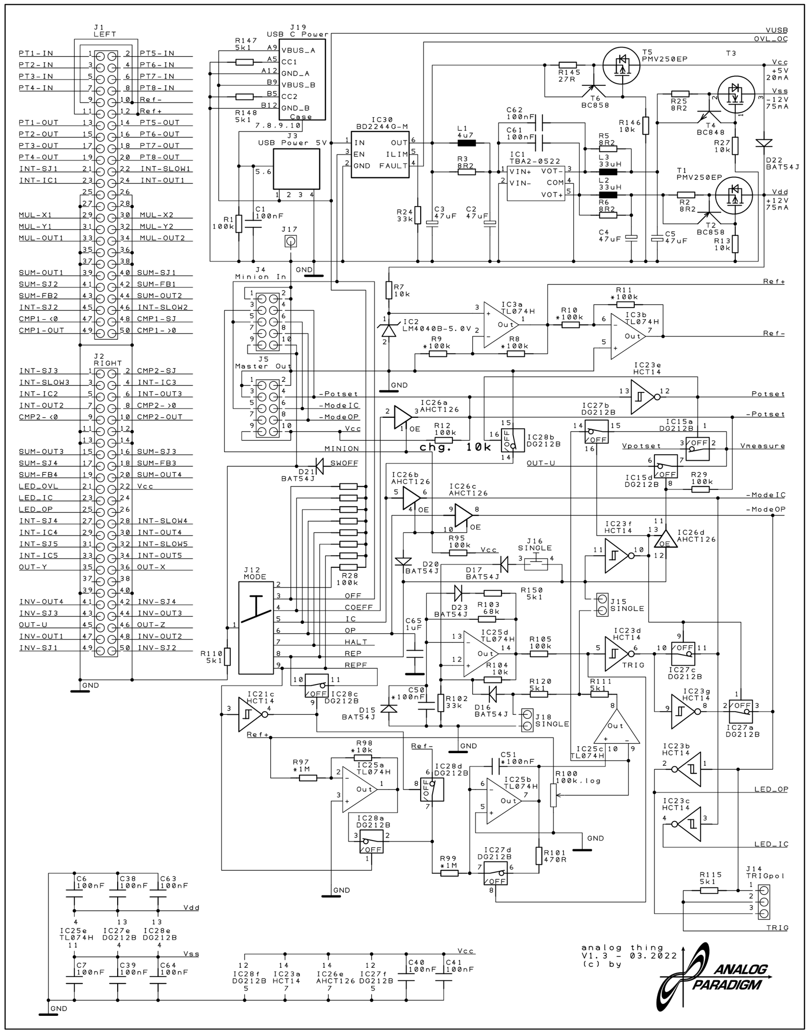
Figure 1 — THAT Base PCB v1.3 schematic sheet 1. The MASTER OUT and MINION IN 10-pin ribbon headers are visible in the upper-left region, feeding the 74LVC245 bus transceiver. The HYBRID 20-pin connector occupies the right-centre of this sheet.
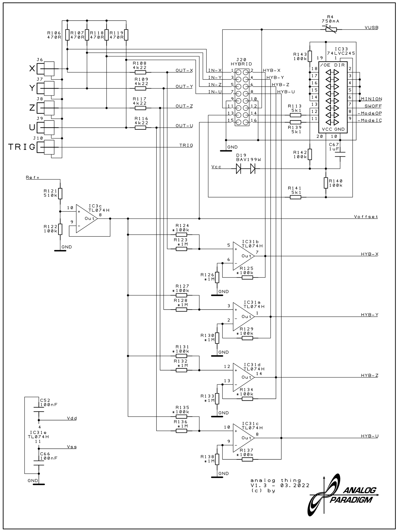
Figure 2 — THAT Base PCB v1.3 schematic sheet 5. This sheet details the HYBRID port signal conditioning: four TL074H op-amp stages (IC31a–d) level-shift and attenuate the four patch-panel output signals from ±10 V to 0–3.3 V. The 74LVC245 transceiver (IC33) handles the digital control lines and the MASTER OUT / MINION IN logic. The ±470 Ω series resistors feeding the RCA phono jacks are also visible.
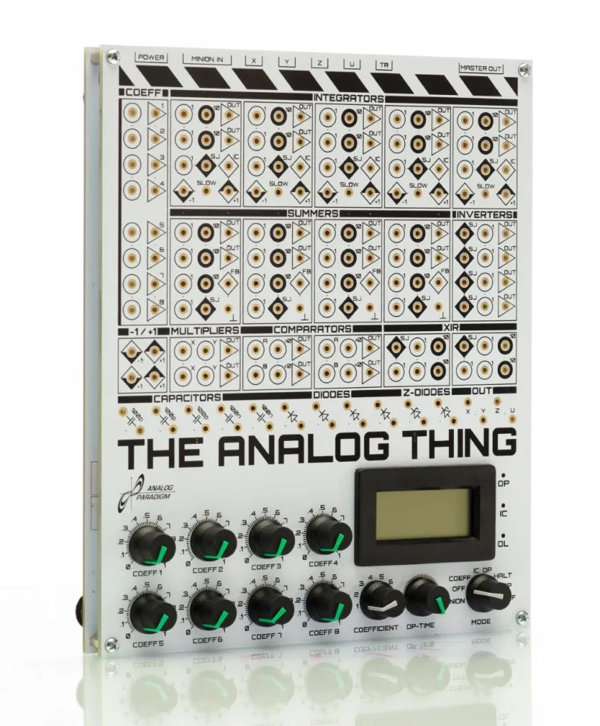
Figure 3 — THAT from the front-left. The rear-panel connectors (USB-C, MINION IN, RCA × 4, TRIGGER, HYBRID, MASTER OUT) are visible on the far edge. A 10-pin ribbon cable connecting two units in a master/minion chain would plug into the MASTER OUT header visible here.
Comments (0)