Heathkit ES-400 · Volume 8
Heathkit ES-400 — Volume 8 — Cheatsheet (field-grade)
Condensed field reference for bench work, patching, and restoration — distilled from Vols 1–7
8.1 Panel 1 — Sub-Assembly Inventory and Tube Map
8.1.1 Complete Sub-Assembly Roster
Table 1 — Complete Sub-Assembly Roster
| Model | Qty | Function | Tubes per Unit | Notes |
|---|---|---|---|---|
| ES-2 | 1 | Amplifier Power Supply | 13 tubes: 1×5651, 3×12AX7, 3×6U8, 2×6080, 1×6BX7, 2×5R4GY, 1×5U4GB | ~43 lb; regulated ±250 V @ 250 mA, −450 V @ 50 mA, 6.3 VAC @ 12 A + 6.3 VAC @ 2.5 A |
| ES-50 | 1 | Reference Power Supply | 2×6X4, 2×6U8, 1×5651 | Regulated ±100 V DC reference rails used by all 15 amplifiers |
| ES-100 | 3 | Initial Condition Power Supply | 2×OB2 per unit | Each supplies 2× floating 100 V; 6 IC voltages total across the three units |
| ES-151 | 1 | Relay Power Supply | None (passive network) | ~50 V; drives the two operational relays on the front panel |
| ES-201 | 15 | DC Operational Amplifier | 3 tubes + 1 NE-51 | Gain ≈ 50,000; output ±100 V @ 10 mA max |
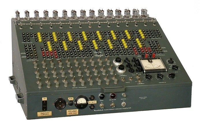
| ES-400 | 1 | Cabinet and Front Panel | — | 364 banana jacks, 52 switches, 38 pots, 14 connectors, 1 DC milliammeter |
| ES-505 | 1 | Repetitive Oscillator | 1×6J6 | 0.6–6 Hz; drives automatic IC/Operate cycling for scope display |
| ES-401 | 1 | Constant-Voltage Transformer | — | 250 VA; conditions AC mains before ES-2; mounts in bottom cabinet bay |
| ES-600 | 1 | Function Generator (optional) | — | Piecewise-linear approximation; 10 segments; connects via rear Varicon socket |
Quick check: a complete Group C system has 25 sub-assemblies (counting 3× ES-100 and 15× ES-201 individually). Missing assemblies most commonly found absent: all or some ES-201 modules (tubes pulled and sold), ES-600 (optional), original patch cords.
8.1.2 ES-201 Tube Complement (per module × 15 modules)
┌─────────────────────────────────────────────────────────────────────┐
│                ES-201 TUBE MAP (one of 15 modules)                  │
│                                                                     │
│  INPUT                                                              │
│  JACKS      ┌────────┐    ┌────────┐    ┌────────┐    OUTPUT       │
│  ──[R_in]──►│ 12AX7  │───►│  6BQ7  │───►│  6BH6  │───►  JACK      │
│             │ Dual   │    │ Dual   │    │ Pentode│        │        │
│             │ Triode │    │ Triode │    │  IF    │        │        │
│             │ High µ │    │ TV     │    │  type  │        │        │
│             └────────┘    └────────┘    └────────┘        │        │
│                                                           │        │
│  FEEDBACK   ◄────────────────────────────────────────────┘        │
│  [C or R plug-in]                                                   │
│                                                                     │
│  OVERLOAD INDICATOR:  NE-51 neon lamp — lights at output saturation │
│  BALANCE POT:  front-panel trim per amplifier                       │
└─────────────────────────────────────────────────────────────────────┘
Table 2 — ES-201 Tube Complement (per module × 15 modules)
| Tube | Type | Function | Replacement Notes |
|---|---|---|---|
| 12AX7 | Dual triode, 9-pin noval | High-gain input stage | Chinese new-production acceptable; ~$9.59 ea from Antique Electronic Supply |
| 6BQ7 | Dual triode, 9-pin noval | Intermediate gain / TV tuner type | NOS preferred; source from eBay/tube dealers |
| 6BH6 | Sharp-cutoff pentode, 7-pin | Output/buffer stage | Common IF amp tube; NOS from eBay |
| NE-51 | Neon indicator lamp | Overload indicator per amplifier | Available new from general electronics suppliers |
Total active vacuum tubes: 45 tubes across the 15 ES-201 modules (3 per module), visible through the top of the cabinet. Additional rectifier/regulator tubes reside inside the ES-2 power supply, bringing the system total to 73 tubes (per Operational Manual / Research Guide; source: ES-400 specification data).
Note — The 12AX7, 6BQ7, and 6BH6 socket types are different (9-pin noval for the first two; 7-pin for the 6BH6). Do not swap socket types during restoration. Verify pin-out against the ES-201 schematic before inserting any tube.
8.2 Panel 2 — Front Panel / Patchbay Quick-Reference
8.2.1 Front Panel Element Count
Table 3 — Front Panel Element Count
| Element | Quantity | Purpose |
|---|---|---|
| Banana-plug jacks | 364 | All signal routing, power taps, reference taps |
| Potentiometers (coefficient) | 30 | Scaling constants 0–1 (10-turn vernier; see Panel 3) |
| Auxiliary 10-turn pots | 2 | Extended-range coefficient setting |
| Total pots | 38 | Includes balance, meter-select, and IC adjust pots |
| Toggle switches | 52 | IC/Operate/Hold per amplifier, relay controls, power |
| Multi-pin connectors | 14 | Internal harness + ES-600 Varicon rear connections |
| DC milliammeter | 1 | Front-panel readout for any selected amplifier output |
8.2.2 Front-Panel Zone Map (top-view, left → right)
┌──────────────────────────────────────────────────────────────────────────────┐
│  ES-400 FRONT PANEL — ZONE OVERVIEW (operator faces this surface)            │
│                                                                              │
│  TOP ROW (tubes visible above):                                              │
│  [AMP 1]  [AMP 2]  [AMP 3] ... [AMP 15]   — 15× ES-201 modules             │
│                                                                              │
│  ┌──────────────────────────────────────────────────────────────────────┐   │
│  │ LEFT SECTION        │ CENTER SECTION          │ RIGHT SECTION        │   │
│  │                     │                         │                      │   │
│  │ HISTORY / AUXILIARY │ MAIN PATCH FIELD        │ COEFFICIENT SET      │   │
│  │ POTS (10-turn × 2)  │ (bulk of 364 jacks)     │ (30 coefficient pots)│   │
│  │                     │                         │                      │   │
│  │ INITIAL CONDITIONS  │ AMPLIFIER SWITCHES      │ METER SELECT GROUP   │   │
│  │ (IC jacks, 6 float) │ (IC / OPERATE per amp)  │ (AMPLIFIER OUTPUT    │   │
│  │                     │                         │  jack + meter)       │   │
│  │ RELAY CONTROLS      │ OPERATE RELAYS (A, B)   │                      │   │
│  │                     │                         │ REFERENCE SUPPLY     │   │
│  │ POWER SWITCHES      │ OSCILLOSCOPE OUTPUTS    │ (±100 V ref jacks)   │   │
│  │ (MAIN / HV / IC)    │ (HORIZ, VERT, GATING)   │                      │   │
│  └──────────────────────────────────────────────────────────────────────┘   │
│                                                                              │
│  METER: DC milliammeter — reads output of any selected ES-201               │
└──────────────────────────────────────────────────────────────────────────────┘
8.2.3 Key Jack / Switch Functions
Table 4 — Key Jack / Switch Functions
| Label / Control | Function | Operating Notes |
|---|---|---|
| AMPLIFIER OUTPUT | Measures selected amp via front meter | Set AMP SELECTOR switch first; remove all inputs before zeroing balance |
| ±100 V REF jacks | ES-50 regulated reference taps | Low-impedance; do not short — connect through coefficient pot |
| IC jacks (6 floating) | Initial condition voltage sources | Floating — isolated from chassis and signal ground; set with IC pot before applying |
| OPERATE / IC / HOLD toggle per amp | Selects amplifier operating mode | IC: amp output held at IC voltage; OPERATE: integrates/sums; HOLD: freezes output |
| RELAY A / B | Operational relay switching | Energized by ES-151 supply; can switch patch connections under program control |
| OSCILLATOR | ES-505 output jack | Drives IC/Operate cycling for repetitive display; 0.6–6 Hz range |
| COEFF SET | Per-pot group: 30 single-turn + 2 ten-turn | Read pot dial; see Panel 3 for exact transfer function |
| HORIZ / VERT / GATING | Oscilloscope output jacks | Route any two amplifier outputs to scope; GATING drives Z-axis unblanking |
| METER (front) | DC milliammeter | Null indicator for balance; reads output voltage scaled by internal resistor |
Note — The connection spacing between jacks is 3/4 in. General Radio double-banana plugs (or equivalent 2 mm banana plugs) are the correct connector type. The Operational Manual specifies polystyrene-type capacitors for integration feedback — do not substitute electrolytic types in integrator feedback positions.
8.3 Panel 3 — Scaling Formula Card
8.3.1 Amplifier Transfer Functions
╔══════════════════════════════════════════════════════════════════════╗
║  SUMMER (resistor feedback, resistor inputs)                        ║
║                                                                     ║
║         e_out = −[ (R_f/R_1)·e_1 + (R_f/R_2)·e_2 + ··· ]        ║
║                                                                     ║
║  Equal resistors → gain = −1 per input (inverter / sign-changer)  ║
║  Mix R values → weighted sum / difference (sign-inverted at output)║
╠══════════════════════════════════════════════════════════════════════╣
║  INTEGRATOR (capacitor feedback, resistor input)                    ║
║                                                                     ║
║         e_out = −(1/RC) · ∫ e_in dt   +  e_IC                     ║
║                                                                     ║
║  R = 1 MΩ, C = 1 µF  →  τ = 1 s  (unity time scale)              ║
║  R = 1 MΩ, C = 0.1 µF →  τ = 0.1 s  (10× time compression)       ║
║  R = 0.1 MΩ, C = 1 µF → τ = 0.1 s  (10× time compression)        ║
║  e_IC sets initial condition at t = 0                               ║
╠══════════════════════════════════════════════════════════════════════╣
║  COEFFICIENT (pot + amplifier)                                      ║
║                                                                     ║
║  Single-turn pot:  k = 0 to 1  (linear, direct reading)            ║
║  10-turn aux pot:  k = 0 to 1  (10× vernier resolution)            ║
║  Combined with gain-10 amp:  k_eff = 0 to 10                       ║
╚══════════════════════════════════════════════════════════════════════╝
8.3.2 Amplitude Scaling Rule
The ES-201 output saturates at ±100 V (hard rail). The NE-51 indicator fires at saturation.
Table 5 — Amplitude Scaling Rule
| Machine variable | Real variable | Scale factor s |
|---|---|---|
| e (volts) | x (real units) | s = e / x |
| e_max = 100 V | x_max (estimate) | s = 100 / x_max |
Danger — Sustained output saturation against a low-impedance load exceeds the 10 mA output rating of the ES-201. Patch verification should always begin with the source (upstream) amplifier outputs disconnected until approximate levels are confirmed on the meter.
8.3.3 Time Scaling Rule
Table 6 — Time Scaling Rule
| Condition | Relation | Effect |
|---|---|---|
| Real time = machine time | τ = RC = 1 s (R=1MΩ, C=1µF) | Display requires slow chart recorder or X-T scope |
| Time compression n:1 | Use RC = 1/n s (e.g. C=0.1µF for 10:1) | Faster solution fits oscilloscope; repetitive mode via ES-505 works well |
| Time expansion 1:n | Use RC = n s (e.g. C=10µF for 10:1) | Slows fast real phenomena to observable machine rate |
8.3.4 Amplitude + Time Scale Combined
For a second-order ODE ẍ + 2ζω_n ẋ + ω_n² x = f(t):
Machine equation (all variables scaled by amplitude factor s, time by β):

  d²X/dτ² + 2ζ(ω_n/β)·dX/dτ + (ω_n/β)²·X = F(τ)/s

  where τ = β·t (machine time),  X = s·x (machine voltage)
  β = time-scale factor (β > 1 → compression)
  s = amplitude scale (V per real unit)

Pot settings:
  damping pot    = 2ζ(ω_n/β) / 10   [normalised to pot range 0–1 if gain=10]
  spring pot     = (ω_n/β)² / 100   [similarly normalised]
See Vol 3 (Scaling and Problem Preparation) for full worked examples.
8.3.5 Standard Plug-In Component Values
Table 7 — Standard Plug-In Component Values
| Component | Value | Time constant (with 1 MΩ) | Use |
|---|---|---|---|
| Feedback resistor | 1 MΩ | — | Unity-gain summer |
| Feedback resistor | 100 kΩ | — | Gain-10 summer |
| Integrating capacitor | 1 µF | 1 s | Standard integration |
| Integrating capacitor | 0.1 µF | 0.1 s | 10× time compression |
| Integrating capacitor | 10 µF | 10 s | 10× time expansion |
| Input resistor | 1 MΩ | — | Unity-weight input |
| Input resistor | 100 kΩ | — | Gain-10 input |
8.4 Panel 4 — Patch Quick-Reference
8.4.1 Signal-Flow Conventions
PATCH CORD COLOR CONVENTION (standard for ES-400 field use)
──────────────────────────────────────────────────────────
  BLACK  ─── Signal ground / reference common
  RED    ─── Positive voltage signal paths
  YELLOW ─── Inter-amplifier signal cables (general)
  GREEN  ─── Feedback paths
  WHITE  ─── Coefficient / pot output connections
  (Any colour may be used — consistency per patch is the rule)
8.4.2 Standard Circuit Patches
INVERTER / SIGN CHANGER
─────────────────────────────────────────────────────────
  e_in ──[1MΩ]──► AMP_n INPUT
                  AMP_n FEEDBACK ──[1MΩ]──┐
                                          │ (connect fb jack back to
                  AMP_n OUTPUT ───────────┘  input bus via 1MΩ)
  e_out = −e_in
  Required whenever a sign flip is needed in a feedback loop.

INTEGRATOR
─────────────────────────────────────────────────────────
  e_in ──[1MΩ]──► AMP_n INPUT
                  AMP_n FEEDBACK ──[1µF]──┐
                  IC SUPPLY ─────────────► IC jack on AMP_n
                  AMP_n MODE SW ──────────  IC → OPERATE to start
  e_out(t) = −(1/RC)∫e_in dt + e_IC(0)

COEFFICIENT MULTIPLIER (gain 0–1)
─────────────────────────────────────────────────────────
  Source ──► POT_k WIPER ──► AMP_n INPUT (via 1MΩ)
  e_out = −k · e_source   (k set by coefficient pot dial)

SECOND-ORDER OSCILLATOR (harmonic oscillator / sine source)
─────────────────────────────────────────────────────────
  [assume ω²X exists]
  AMP_1 IN ──[1MΩ]── from AMP_2 output via pot (ω² setting)
  AMP_1 FDBK ──[1µF]──  →  AMP_1 OUT = −Ẋ
  AMP_2 IN ──[1MΩ]── from AMP_1 output
  AMP_2 FDBK ──[1µF]──  →  AMP_2 OUT = +X (sine)
  AMP_1 OUT = −Ẋ (cosine, 90° offset)
  Frequency: f = ω/(2π);  pot set to ω² / 100

SPRING-MASS-DAMPER  (3 amplifiers)
─────────────────────────────────────────────────────────
  AMP_1 (summer):
    IN_1 ──[1MΩ]── F(t) forcing function
    IN_2 ──[pot_c]── −Ẋ (from AMP_2 out)      [damping]
    IN_3 ──[pot_k]── −X  (from AMP_3 out)      [spring]
    FDBK ──[1MΩ]──  → AMP_1 OUT = −Ẍ
  AMP_2 (integrator):
    IN  ──[1MΩ]── AMP_1 OUT (= −Ẍ)
    FDBK──[1µF]──  → AMP_2 OUT = +Ẋ
  AMP_3 (integrator):
    IN  ──[1MΩ]── AMP_2 OUT (= +Ẋ)  [invert if needed]
    FDBK──[1µF]──  → AMP_3 OUT = −X
  Feedback: AMP_3 OUT → pot_k → AMP_1 IN_3
            AMP_2 OUT → pot_c → AMP_1 IN_2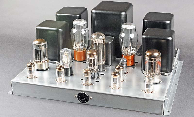
(reference — courtesy Nuts & Volts / David Goodsell)
8.4.3 Patch Signal-Flow Diagram (General Form)
<svg xmlns="http://www.w3.org/2000/svg" viewBox="0 0 700 200" font-family="monospace" font-size="11">
  <!-- Reference supply -->
  <rect x="10" y="70" width="80" height="40" fill="#d4e8ff" stroke="#336"/>
  <text x="50" y="88" text-anchor="middle" font-size="10">±100V</text>
  <text x="50" y="101" text-anchor="middle" font-size="10">REF (ES-50)</text>

  <!-- Coefficient pot -->
  <rect x="120" y="70" width="70" height="40" fill="#ffe8c0" stroke="#963"/>
  <text x="155" y="88" text-anchor="middle" font-size="10">COEFF</text>
  <text x="155" y="101" text-anchor="middle" font-size="10">POT k</text>

  <!-- Summer amp -->
  <polygon points="220,60 280,90 220,120" fill="#c8ffc8" stroke="#363"/>
  <text x="240" y="88" font-size="10">SUM</text>
  <text x="240" y="101" font-size="10">AMP</text>

  <!-- Integrator amp -->
  <polygon points="320,60 380,90 320,120" fill="#ffd0d0" stroke="#633"/>
  <text x="338" y="88" font-size="10">INT</text>
  <text x="338" y="101" font-size="10">AMP</text>

  <!-- Second integrator -->
  <polygon points="420,60 480,90 420,120" fill="#ffd0d0" stroke="#633"/>
  <text x="438" y="88" font-size="10">INT</text>
  <text x="438" y="101" font-size="10">AMP</text>

  <!-- Output box -->
  <rect x="510" y="70" width="70" height="40" fill="#e8ffe8" stroke="#363"/>
  <text x="545" y="88" text-anchor="middle" font-size="10">SCOPE /</text>
  <text x="545" y="101" text-anchor="middle" font-size="10">METER</text>

  <!-- Connections -->
  <line x1="90" y1="90" x2="120" y2="90" stroke="#333" stroke-width="1.5"/>
  <line x1="190" y1="90" x2="220" y2="90" stroke="#333" stroke-width="1.5"/>
  <line x1="280" y1="90" x2="320" y2="90" stroke="#333" stroke-width="1.5"/>
  <line x1="380" y1="90" x2="420" y2="90" stroke="#333" stroke-width="1.5"/>
  <line x1="480" y1="90" x2="510" y2="90" stroke="#333" stroke-width="1.5"/>

  <!-- Feedback loop -->
  <path d="M 480,90 L 480,160 L 155,160 L 155,110" stroke="#c00" stroke-width="1.5" fill="none" stroke-dasharray="4,2"/>
  <text x="300" y="175" text-anchor="middle" font-size="10" fill="#c00">FEEDBACK PATH (sign loop closes via inverter if needed)</text>

  <!-- IC input -->
  <line x1="350" y1="60" x2="350" y2="40" stroke="#00a" stroke-width="1.5" stroke-dasharray="3,2"/>
  <text x="355" y="35" font-size="9" fill="#00a">IC supply</text>

  <!-- Labels -->
  <text x="50" y="55" text-anchor="middle" font-size="9">Reference</text>
  <text x="155" y="55" text-anchor="middle" font-size="9">Scale k</text>
  <text x="250" y="55" text-anchor="middle" font-size="9">−Σ</text>
  <text x="350" y="55" text-anchor="middle" font-size="9">−∫</text>
  <text x="450" y="55" text-anchor="middle" font-size="9">−∫</text>
</svg>
8.5 Panel 5 — Power-Up / Power-Down Checklist
8.5.1 Power-Up Sequence
Danger — The ES-2 supply develops −450 V and ±250 V rails. The ES-50 operates at ±100 V. All surfaces inside the cabinet are live during operation. The front panel hinges forward (it is very heavy) — install locking tip-up support rods before reaching inside.
PRE-POWER INSPECTION
[ ] All 15 ES-201 modules seated and locked in their slots
[ ] All tube sockets occupied — no open sockets on powered modules
[ ] Front panel closed and latched
[ ] No patch cords installed yet (reduces transient load)
[ ] Confirm all amplifier MODE switches are in IC position
[ ] Confirm MAIN POWER switch is OFF
[ ] Confirm COEFFICIENT SET pot group switches to "POT" position (not "EXT")

POWER-UP (normal sequence)
[ ] 1. Apply AC mains — MAIN POWER switch ON
[ ] 2. Allow 60 s minimum warm-up before applying high voltage
        (Operational Manual specifies: "Allow tubes to warm up for at least
         30 minutes before working with the computer" — abbreviated warmup
         acceptable for quick checks but full thermal settle takes 30 min)
[ ] 3. HIGH VOLTAGE switch ON — verifies ±250V and −450V rails
[ ] 4. Confirm ES-50 ±100 V reference: check ref jacks with DVM
[ ] 5. IC POWER switch ON — brings up ES-100 and ES-151 supplies
[ ] 6. Verify relay supply: ES-151 2× 50 V rails
[ ] 7. Balance all 15 ES-201 amplifiers (see Balance Procedure below)
[ ] 8. Install patch cords per problem setup
[ ] 9. Set initial condition voltages via IC pots
[ ] 10. Flip MODE switches from IC → OPERATE to run

BALANCE PROCEDURE (per ES-201, repeat for all 15)
[ ] a. Connect AMPLIFIER OUTPUT jack to front-panel meter via selector switch
[ ] b. Short all input jacks to ground (remove plug-in input resistors)
[ ] c. Adjust BALANCE pot for this amplifier until meter reads zero
[ ] d. Reinstall input and feedback plug-in components
[ ] e. Re-check: meter should return near zero with all inputs undriven
8.5.2 Power-Down Sequence
POWER-DOWN (normal sequence)
[ ] 1. Flip all MODE switches to IC (freezes integrator outputs safely)
[ ] 2. IC POWER switch OFF
[ ] 3. HIGH VOLTAGE switch OFF
[ ] 4. Allow 60 s for capacitors to partially discharge
[ ] 5. MAIN POWER switch OFF
[ ] 6. Allow 5 min before opening cabinet or touching internal components
         (ES-2 main filter caps can hold dangerous charge; verify with
          DVM across each electrolytic cap before touching any internal point)
Danger — Do NOT assume filter capacitors are discharged after power-off. Measure before touching. The −450 V rail is the most hazardous; it discharges through the bleeder resistor network but this takes time. See Panel 8 (Safety Card).
8.6 Panel 6 — Restoration Inspection and Recap Checklist
8.6.1 Pre-Restoration Assessment
PHYSICAL INVENTORY — check before ordering any parts
[ ] Count ES-201 modules present (target: 15; often fewer)
[ ] Count tubes per module (should be 12AX7 + 6BQ7 + 6BH6 + NE-51 each)
[ ] ES-600 Function Generator present? (optional; often missing)
[ ] All 364 banana jacks present and not stripped?
[ ] Original patch cords present?
[ ] Daca-Ware knobs all present and matching?
[ ] Front panel silk-screening legible?
[ ] Cabinet interior panels present (8 panels)?
[ ] ES-401 transformer and all supply transformers/chokes present?
8.6.2 ES-2 Amplifier Power Supply Recap
Table 8 — ES-2 Amplifier Power Supply Recap
| Component | Spec | Qty | Source |
|---|---|---|---|
| Main filter electrolytic (large axial) | 20 µF @ 350 V through 70 µF @ 350 V (verify exact values on each cap) | 16 | Antique Electronic Supply (TubesAndMore.com) |
| Smaller electrolytic caps | Various, verify in-circuit | All present | AES / Mouser |
| Paper / wax caps | All values — replace regardless of reading | All present | AES, Mouser, Digi-Key |
| Carbon composition resistors (drifted) | Replace with 1% metal film equivalents | All | Mouser / Digi-Key |
Note — Do NOT attempt to reform the ES-2 electrolytics. Age, storage conditions, and the extended power-off period make reforming unreliable on a one-of-a-kind machine. Replace all electrolytics unconditionally.
8.6.3 ES-201 Operational Amplifier Recap (per module × 15)
Table 9 — ES-201 Operational Amplifier Recap (per module × 15)
| Component | Action | Notes |
|---|---|---|
| All resistors | Measure before removing; replace with 1% metal film | 1% types were standard even originally; copper-oxide corrosion visible on metal end-caps indicates replacement needed |
| All capacitors | Replace unconditionally | Use polystyrene or silver mica for feedback positions; electrolytics for supply bypass only |
| 3 tube sockets (9-pin noval × 2, 7-pin × 1) | Replace with new | Old phenolic sockets oxidize and cause intermittent contact |
| PCB traces | Inspect before and after desoldering | Two pad lifts per board are normal per the Goodsell restoration; repair with fine-gauge wire |
| NE-51 neon lamp | Replace if not lighting at overload | Standard NE-51; available new |
| Module housing (sheet metal) | Clean, prime, repaint | Satin black spray paint; verify no shorts to PCB after painting |
8.6.4 Power Supply Checklist (ES-50, ES-100, ES-151)
[ ] ES-50 (reference supply):  replace all electrolytics and paper caps
[ ] ES-100 (×3 IC supplies):   replace all electrolytics and paper caps;
                                verify floating isolation — neither terminal
                                should have continuity to chassis ground
[ ] ES-151 (relay supply):     replace all electrolytics and paper caps
8.6.5 Cabinet Cosmetics
Table 10 — Cabinet Cosmetics
| Item | Procedure | Cost Reference |
|---|---|---|
| 8 interior steel panels | Sandblast to bare metal; powder-coat textured gray inside and out | ~$180 for all 8 (Goodsell, 2019) |
| Star-lock washers | Install under all panel screws to cut through powder coat and maintain chassis ground continuity | Hardware store |
| Front panel masking tape residue | Remove by hand (fingernail preferred); then Meguiar’s Ultimate Compound; finish with 2 coats Meguiar’s Cleaner Wax | ~$30 total |
| Missing or damaged knobs | Daca-Ware knobs; source from vintage Heathkit MM-1 VOM on eBay | $3–$20 per knob |
| Missing silk-screened labels | Custom dry-transfer (rub-down) sheet from CustomRubOnTransfers.com | ~$65/sheet |
| Transformer / choke cans (rusty) | Disassemble; clean; prime; satin black spray paint | ~$10–$20 paint |
(reference — courtesy Nuts & Volts / David Goodsell)
8.6.6 ES-201 Tube Sourcing Quick-Reference
Table 11 — ES-201 Tube Sourcing Quick-Reference
| Tube | Preferred Type | Source | Approx. Cost (2019 ref.) |
|---|---|---|---|
| 12AX7 × 15 | Chinese new-production | Antique Electronic Supply | ~$9.59 ea |
| 6BQ7 × 15 | NOS vintage | eBay, tube dealers | Varies |
| 6BH6 × 15 | NOS vintage | eBay (common IF type) | Varies |
| NE-51 × 15+ | New production | Any electronics supplier | Cents ea |
8.7 Panel 7 — Troubleshooting Quick-Triage
8.7.1 Symptom → Probable Cause → First Check
Table 12 — Symptom → Probable Cause → First Check
| Symptom | Probable Cause(s) | First Check |
|---|---|---|
| No power, no pilot light | MAIN POWER switch, blown fuse, ES-401 transformer | Check fuse on ES-2; verify AC input at ES-401 primary |
| HV rails absent (no ±250 V) | ES-2 rectifier tubes, open filter cap, blown fuse | Measure B+ at ES-2 output terminals with DVM |
| ±100 V reference wrong | ES-50 regulation failure, bad zener or tube | Measure ES-50 output directly; check reference jack on panel |
| All 15 amps unbalanced (meter won’t null) | ES-50 reference rail wrong, ES-2 supply out of spec | Balance requires stable ±100 V from ES-50 first |
| Single amp won’t balance | Bad 12AX7 (input stage), dirty pot wiper | Swap 12AX7 first (most likely); clean balance pot |
| NE-51 always lit on one module | Amp oscillating, missing or wrong feedback component, bad 6BH6 | Check feedback jack — open feedback → oscillation → saturation |
| Integrator runs away | Positive feedback instead of negative; sign error in patch | Trace signal path; add inverter (sign-changer) in loop |
| Solution drifts at HOLD | Leaky integrating capacitor, 12AX7 grid current | Replace integrating cap (polystyrene is best); check 12AX7 |
| IC won’t set correctly | ES-100 supply floating isolation lost | Check that neither IC terminal shows continuity to chassis |
| ES-505 oscillator not cycling | Bad tube or cap in oscillator | Check ES-505 output with scope at OSCILLATOR jack |
| Meter reads off-scale | Amplifier output saturated (NE-51 should also light) | Check patch: likely a sign error or missing initial condition |
| Repetitive display unstable on scope | ES-505 frequency not matched to scope sweep | Adjust ES-505 pot; or use scope’s external trigger from GATING jack |
| Function generator (ES-600) wrong shape | Segment slope pots mis-set, bad diode | Recalibrate slope/break voltage pots; check diodes (4× dual bias diodes on main panel also) |
| Front panel jack intermittent | Corroded banana jack contact | Clean with DeOxit; replace stripped jacks (banana jacks from eBay) |
8.7.2 ES-201 Single-Module Fault Isolation Procedure
STEP 1 — Isolate module
  Remove all patch cords connected to the suspect amp.
  Set its MODE switch to IC.

STEP 2 — Check tube seating
  Remove and reseat all three tubes. Clean socket pins with DeOxit.

STEP 3 — Static balance check
  Short input summing junction to ground.
  Set MODE to OPERATE.
  Measure output at AMPLIFIER OUTPUT jack.
  Should read within ±2 V of zero after balance pot adjustment.
  → If cannot null: suspect 12AX7 input stage or balance pot.

STEP 4 — Open-loop gain check
  Apply a known small signal (~1 V) via 1 MΩ input resistor.
  With NO feedback component, output should immediately saturate ±100 V.
  → If not: check 6BQ7 and 6BH6 stages.

STEP 5 — Closed-loop summer check
  Install 1 MΩ input + 1 MΩ feedback.
  Apply 50 V reference. Output should be −50 V ±1 V.
  → If wrong gain: resistor values suspect; check plug-in components.

STEP 6 — Integrator check
  Install 1 MΩ input + 1 µF feedback. Set IC to 0 V.
  Apply +10 V input. Output should ramp at −10 V/s.
  → If ramps wrong direction: sign error in patch.
  → If ramps too fast/slow: capacitor value wrong.
  → If drifts with zero input: leaky cap or grid current.
8.7.3 Power Supply Voltage Quick-Check Table
Table 13 — Power Supply Voltage Quick-Check Table
| Test Point | Expected Value | Tolerance | Note |
|---|---|---|---|
| ES-2 +250 V rail | +250 V DC | ±5% | Regulated; check at supply terminal strip |
| ES-2 −250 V rail | −250 V DC | ±5% | Regulated |
| ES-2 −450 V rail | −450 V DC | ±5% | Regulated; highest voltage in system |
| ES-2 heater AC (winding 1) | 6.3 VAC | ±5% | @ 12 A max; measure at ES-201 socket pins |
| ES-2 heater AC (winding 2) | 6.3 VAC | ±5% | @ 2.5 A max; auxiliary filament winding |
| ES-50 +100 V | +100 V DC | ±1% | Reference; tight regulation required |
| ES-50 −100 V | −100 V DC | ±1% | Reference |
| ES-100 (each IC supply) | 0–100 V floating | Set by IC pot | Floating — isolated from ground |
| ES-151 relay supply | 2× 50 V DC | ±10% | Less critical; relay pull-in only |
8.8 Panel 8 — Safety Card (High Voltage)
Danger — The ES-400 operates at voltages that are immediately lethal. The ES-2 supply develops −450 V and ±250 V DC. The ES-50 develops ±100 V. The ES-100 IC supplies each develop up to 100 V floating. None of these voltages are safe to contact. A 50 mA shock across the chest is fatal; the ES-2 is rated 250 mA @ ±250 V.
8.8.1 Hazard Map
╔═══════════════════════════════════════════════════════════════════════╗
║  ES-400 HIGH-VOLTAGE HAZARD MAP                                      ║
║                                                                      ║
║  ZONE A — ES-2 Power Supply (~43 lb chassis, rear-lower cabinet)    ║
║  ┌─────────────────────────────────────────────────────────────┐    ║
║  │  −450 V @ 50 mA   ← HIGHEST RAIL — MOST DANGEROUS          │    ║
║  │  +250 V @ 250 mA  ← PLATE SUPPLY (lethal current)          │    ║
║  │  −250 V @ 250 mA  ← PLATE SUPPLY (lethal current)          │    ║
║  │  Bleeder resistors present; still dangerous minutes post-off │    ║
║  └─────────────────────────────────────────────────────────────┘    ║
║                                                                      ║
║  ZONE B — ES-50 Reference Supply (upper rear)                       ║
║  ┌─────────────────────────────────────────────────────────────┐    ║
║  │  +100 V / −100 V DC  ← hazardous; cardiac threshold ~50mA  │    ║
║  └─────────────────────────────────────────────────────────────┘    ║
║                                                                      ║
║  ZONE C — ES-100 IC Supplies (×3, upper row)                        ║
║  ┌─────────────────────────────────────────────────────────────┐    ║
║  │  Up to 100 V FLOATING — isolated from chassis ground        │    ║
║  │  Both terminals can be above or below ground potential      │    ║
║  └─────────────────────────────────────────────────────────────┘    ║
║                                                                      ║
║  ZONE D — Front Panel Jacks (operator-accessible)                   ║
║  ┌─────────────────────────────────────────────────────────────┐    ║
║  │  ±100 V present at REF jacks and AMPLIFIER OUTPUT jacks     │    ║
║  │  during operation — do not probe with bare fingers          │    ║
║  └─────────────────────────────────────────────────────────────┘    ║
║                                                                      ║
║  ZONE E — ES-201 Tube Tops (visible, accessible from above)         ║
║  ┌─────────────────────────────────────────────────────────────┐    ║
║  │  Tube pins near sockets: −450 V / +250 V present on pins   │    ║
║  │  during operation. Never probe pins with power on.          │    ║
║  └─────────────────────────────────────────────────────────────┘    ║
╚═══════════════════════════════════════════════════════════════════════╝
8.8.2 Safety Rules — Non-Negotiable
Danger — These rules are not suggestions. Violation of any of them can be lethal.
-
One hand in pocket rule. When probing internal points with power applied, keep the non-probe hand behind the back or in a pocket. This prevents a current path across the chest through both arms.
-
Measure before touching. After power-down, measure voltage across every large electrolytic capacitor in the ES-2 with a DVM before contacting any internal point. Bleeder resistors discharge slowly; the −450 V rail may retain lethal charge for several minutes.
-
Never open the cabinet alone. High-voltage work requires a second person present and aware of the hazard.
-
Do not defeat interlocks or safety hardware. The ES-400 chassis ground is electrically isolated from signal ground by design (see Vol 2). Do not connect chassis to signal ground to “fix” a ground loop — this is intentional design.
-
Insulated probes only. Use 1000 V CAT-II rated probes minimum for all internal measurements. Standard 600 V probes are insufficient for the −450 V rail if probe insulation is degraded.
-
Variac bring-up for post-restoration first power. After any significant restoration work, bring up AC mains voltage gradually via a Variac (0 → 120 V over 10–15 minutes) while monitoring supply output rails with a DVM. This limits inrush current and allows early detection of leaky capacitors before they fail catastrophically.
-
HV capacitors in the ES-2. The 16 large axial electrolytics can store significant energy. Even after bleeder discharge, treat them as charged until measured. Short them with a 10 kΩ, 5 W resistor across the terminals (not a direct short — the resistor limits discharge current).
-
Tube removal with power off only. Never insert or remove ES-201 modules or individual tubes with power applied.
8.8.3 Emergency First Aid (electrical shock)
Danger — In the event of electric shock, do NOT touch the victim until the power source is confirmed off. Switch off the MAIN POWER switch, or pull the AC plug. Then call emergency services immediately. Even if the victim appears conscious, cardiac arrest can be delayed by minutes following high-voltage shock.
8.9 System Block Diagram
<svg xmlns="http://www.w3.org/2000/svg" viewBox="0 0 760 420" font-family="monospace" font-size="10">
  <!-- Title -->
  <text x="380" y="18" text-anchor="middle" font-size="13" font-weight="bold">Heathkit ES-400 — System Power and Signal Block Diagram</text>

  <!-- AC Mains -->
  <rect x="10" y="35" width="80" height="35" fill="#fffacd" stroke="#999" stroke-width="1.5"/>
  <text x="50" y="52" text-anchor="middle">110 VAC</text>
  <text x="50" y="63" text-anchor="middle">60 Hz</text>

  <!-- ES-401 -->
  <rect x="120" y="35" width="80" height="35" fill="#ffe4b5" stroke="#c90" stroke-width="1.5"/>
  <text x="160" y="52" text-anchor="middle">ES-401 CVT</text>
  <text x="160" y="63" text-anchor="middle">250 VA</text>

  <!-- ES-2 -->
  <rect x="230" y="25" width="100" height="55" fill="#ffd0d0" stroke="#c00" stroke-width="2"/>
  <text x="280" y="42" text-anchor="middle" font-weight="bold">ES-2</text>
  <text x="280" y="54" text-anchor="middle">+250V/250mA</text>
  <text x="280" y="64" text-anchor="middle">−250V/250mA</text>
  <text x="280" y="74" text-anchor="middle">−450V/50mA</text>

  <!-- ES-50 -->
  <rect x="230" y="100" width="100" height="40" fill="#d0d0ff" stroke="#009" stroke-width="1.5"/>
  <text x="280" y="117" text-anchor="middle" font-weight="bold">ES-50</text>
  <text x="280" y="130" text-anchor="middle">±100V REF</text>

  <!-- ES-100 x3 -->
  <rect x="230" y="160" width="100" height="55" fill="#d0ffd0" stroke="#060" stroke-width="1.5"/>
  <text x="280" y="177" text-anchor="middle" font-weight="bold">ES-100 ×3</text>
  <text x="280" y="189" text-anchor="middle">IC Supplies</text>
  <text x="280" y="201" text-anchor="middle">6× floating</text>
  <text x="280" y="211" text-anchor="middle">0–100V ea</text>

  <!-- ES-151 -->
  <rect x="230" y="235" width="100" height="40" fill="#ffe0ff" stroke="#909" stroke-width="1.5"/>
  <text x="280" y="252" text-anchor="middle" font-weight="bold">ES-151</text>
  <text x="280" y="265" text-anchor="middle">Relay 2×50V</text>

  <!-- ES-505 -->
  <rect x="230" y="295" width="100" height="40" fill="#fffff0" stroke="#990" stroke-width="1.5"/>
  <text x="280" y="312" text-anchor="middle" font-weight="bold">ES-505</text>
  <text x="280" y="325" text-anchor="middle">Osc 0.6–6Hz</text>

  <!-- 15x ES-201 -->
  <rect x="380" y="80" width="140" height="130" fill="#fff0e0" stroke="#c60" stroke-width="2"/>
  <text x="450" y="100" text-anchor="middle" font-weight="bold">15× ES-201</text>
  <text x="450" y="114" text-anchor="middle">DC Op-Amp</text>
  <text x="450" y="126" text-anchor="middle">Gain ≈ 50,000</text>
  <text x="450" y="138" text-anchor="middle">Out: ±100V</text>
  <text x="450" y="150" text-anchor="middle">@ 10mA max</text>
  <text x="450" y="162" text-anchor="middle">Tubes: 12AX7</text>
  <text x="450" y="174" text-anchor="middle">6BQ7, 6BH6</text>
  <text x="450" y="186" text-anchor="middle">+ NE-51 lamp</text>
  <text x="450" y="198" text-anchor="middle">per module</text>

  <!-- Front panel -->
  <rect x="380" y="230" width="140" height="95" fill="#e0f0ff" stroke="#369" stroke-width="2"/>
  <text x="450" y="248" text-anchor="middle" font-weight="bold">ES-400 PANEL</text>
  <text x="450" y="260" text-anchor="middle">364 banana jacks</text>
  <text x="450" y="272" text-anchor="middle">52 switches</text>
  <text x="450" y="284" text-anchor="middle">38 pots</text>
  <text x="450" y="296" text-anchor="middle">1 milliammeter</text>
  <text x="450" y="308" text-anchor="middle">14 connectors</text>
  <text x="450" y="318" text-anchor="middle">Patch field</text>

  <!-- Scope -->
  <rect x="580" y="120" width="100" height="45" fill="#f0fff0" stroke="#393" stroke-width="1.5"/>
  <text x="630" y="139" text-anchor="middle">OSCILLOSCOPE</text>
  <text x="630" y="151" text-anchor="middle">XY / XT mode</text>

  <!-- ES-600 optional -->
  <rect x="580" y="280" width="100" height="40" fill="#f5f5f5" stroke="#999" stroke-width="1" stroke-dasharray="4,2"/>
  <text x="630" y="297" text-anchor="middle">ES-600</text>
  <text x="630" y="309" text-anchor="middle">Func. Gen. (opt)</text>

  <!-- Power connections (red dashed = HV) -->
  <line x1="90" y1="52" x2="120" y2="52" stroke="#c90" stroke-width="2"/>
  <line x1="200" y1="52" x2="230" y2="52" stroke="#c90" stroke-width="2"/>

  <!-- ES-2 feeds ES-201 -->
  <line x1="330" y1="45" x2="370" y2="145" stroke="#c00" stroke-width="1.5" stroke-dasharray="4,2"/>
  <text x="340" y="95" font-size="9" fill="#c00">±250V, −450V</text>
  <text x="340" y="105" font-size="9" fill="#c00">6.3VAC heat</text>

  <!-- ES-50 feeds front panel reference jacks -->
  <line x1="330" y1="120" x2="380" y2="277" stroke="#009" stroke-width="1.5" stroke-dasharray="4,2"/>
  <text x="333" y="185" font-size="9" fill="#009">±100V ref</text>

  <!-- ES-100 feeds front panel IC jacks -->
  <line x1="330" y1="188" x2="380" y2="290" stroke="#060" stroke-width="1.5" stroke-dasharray="4,2"/>

  <!-- ES-201 → Front panel -->
  <line x1="450" y1="210" x2="450" y2="230" stroke="#c60" stroke-width="2"/>

  <!-- Front panel → Scope -->
  <line x1="520" y1="277" x2="580" y2="145" stroke="#363" stroke-width="1.5"/>
  <text x="535" y="220" font-size="9">Signal out</text>

  <!-- ES-505 → Front panel -->
  <line x1="330" y1="315" x2="380" y2="315" stroke="#990" stroke-width="1.5"/>
  <text x="335" y="310" font-size="8">0.6–6Hz</text>

  <!-- ES-600 optional connection -->
  <line x1="520" y1="300" x2="580" y2="300" stroke="#999" stroke-width="1" stroke-dasharray="3,2"/>

  <!-- ES-401 → ES-50, ES-100, ES-151 -->
  <line x1="160" y1="70" x2="160" y2="265" stroke="#c90" stroke-width="1" stroke-dasharray="2,2"/>
  <line x1="160" y1="120" x2="230" y2="120" stroke="#c90" stroke-width="1" stroke-dasharray="2,2"/>
  <line x1="160" y1="188" x2="230" y2="188" stroke="#c90" stroke-width="1" stroke-dasharray="2,2"/>
  <line x1="160" y1="255" x2="230" y2="255" stroke="#c90" stroke-width="1" stroke-dasharray="2,2"/>
  <line x1="160" y1="315" x2="230" y2="315" stroke="#c90" stroke-width="1" stroke-dasharray="2,2"/>

  <!-- Legend -->
  <rect x="10" y="350" width="330" height="60" fill="#f9f9f9" stroke="#999"/>
  <text x="170" y="365" text-anchor="middle" font-weight="bold">LEGEND</text>
  <line x1="20" y1="378" x2="60" y2="378" stroke="#c00" stroke-width="1.5" stroke-dasharray="4,2"/>
  <text x="65" y="382">High-voltage power (ES-2)</text>
  <line x1="20" y1="393" x2="60" y2="393" stroke="#c90" stroke-width="1.5" stroke-dasharray="2,2"/>
  <text x="65" y="397">AC distribution (ES-401 → supplies)</text>
  <line x1="180" y1="378" x2="220" y2="378" stroke="#363" stroke-width="1.5"/>
  <text x="225" y="382">Signal path</text>
  <line x1="180" y1="393" x2="220" y2="393" stroke="#999" stroke-width="1" stroke-dasharray="3,2"/>
  <text x="225" y="397">Optional / ES-600</text>
</svg>
8.10 Quick ES-400 vs. EC-1 Comparison
Table 14 — Quick ES-400 vs. EC-1 Comparison
| Parameter | ES-400 (H-1) | EC-1 (desktop) |
|---|---|---|
| Op-amp modules | 15× ES-201 | 9× (same ES-201 circuit) |
| Banana jacks | 364 | Fewer |
| Weight | 168 lb | ~35 lb |
| Original price | $945 (Group C) | ~$200 |
| Power | ~450 W | Lower |
| Tube count | 73 total | ~28 |
| Cabinet | Floor-standing, 2-bay | Desktop |
| Coefficient pots | 30 + 2 auxiliary 10-turn | Fewer |
| IC supplies | 3× ES-100 (6 floating voltages) | 1–2 |
| ES-505 oscillator | Included | Optional |
| Programming method | Identical — same ES-201 | Same |
Note — The EC-1 Operational Manual (freely available) provides the most complete programming tutorial for the ES-201 op-amp method and is directly applicable to the ES-400. See Vol 1 for full citation.
8.11 Cross-Volume Reference Index
Table 15 — Cross-Volume Reference Index
| Topic | Volume |
|---|---|
| Full system overview, history, and provenance | Vol 1 — Overview & history |
| Hardware architecture, power supplies, ES-201 circuit | Vol 2 — Hardware & architecture |
| Computing elements, patchbay, integrator, summer, bias diodes | Vol 3 — Computing elements & patchbay |
| Acquisition, inspection, restoration, recap, bring-up | Vol 4 — Acquisition & restoration |
| Programming methodology: scaling, patching, reading results | Vol 5 — Programming |
| Sample programs and demonstrations (six worked examples) | Vol 6 — Sample programs |
| Modern extensions, ADC/DAC bridge, hybrid use | Vol 7 — Modern extensions |
| This cheatsheet (condensed field reference) | Vol 8 — Cheatsheet |
Comments (0)