Heathkit ES-400 · Volume 1
Heathkit ES-400 — Volume 1 — Overview & history
What the machine is, how it came to exist, what it contains, and where each topic is treated in Vols 2–8
1.1 About this Volume
Volume 1 is the entry point to an eight-volume engineer-grade reference for the Heathkit ES-400 Electronic Analog Computer, also sold under the designations H-1 and Heath H1. The goal of the series is to document every measurable, reproducible fact about the ES-400 at the level of detail needed for restoration, calibration, and analytical use — and to explain the underlying analog-computation theory without condescension toward the reader. All electrical values, sub-assembly model numbers, tube types, and voltages cited throughout the series are sourced from the original Heath operational manual, the 1956 Heath sales brochure (Computer History Museum archive accession 102646297), and David Goodsell’s 2019 restoration record published in Nuts & Volts.
1.1.1 How to use this series
The eight volumes are organized so that a reader restoring an ES-400 from scratch can work front-to-back, while a reader interested only in theory or programming can enter at Vol 3, 4, or 5. Cross-references use the shorthand “Vol N” throughout.
1.1.2 Depth-index table — ES-400 volume series
Table 1 — Depth-index table — ES-400 volume series
| Vol | Title | Primary audience | Key topics |
|---|---|---|---|
| 1 | Overview & history | All readers | What the machine is; commercial history; physical tour; specifications quick-table |
| 2 | Power architecture | Restoration engineer | ES-2 amplifier supply (±250 V, −450 V); ES-50 reference supply (±100 V); ES-100 IC supplies; ES-151 relay supply; ES-401 voltage-regulator transformer; power sequencing; full DC power tree |
| 3 | ES-201 operational amplifier | Circuit-level analyst | 12AX7 / 6BQ7 / 6BH6 tube circuit; gain measurement; balancing procedure; NE-51 overload indicator |
| 4 | Front panel & patch field | All practitioners | 364-jack field map; 52-switch functions; 30 coefficient pots + 2 auxiliary 10-turn pots; initial-condition network; operational relay pair; ES-505 repetitive oscillator |
| 5 | Analog computation theory | Engineers / students | ODE formulation; scaling; time scaling; amplitude scaling; block-diagram notation; error analysis |
| 6 | Programming & worked examples | Practitioners | Patch setups; IC setting; repetitive-mode oscilloscope display; eight worked programs from free-fall to spring-mass-damper |
| 7 | Restoration manual | Restorer | Full recap BOM; step-by-step sub-assembly procedure; front-panel refinishing; powder-coat spec; tube sourcing; alignment |
| 8 | Modern peripherals & hybrid use | Experimenters | Oscilloscope interface; ADC/DAC bridge to Raspberry Pi; function-generator input scaling; hybrid-computer architecture |
Note — Volume 2 treats power in the depth required for safe first energisation of a restored unit. Any operator who has not yet read Vol 2 should do so before applying mains power to an ES-400 that has been in storage.
1.2 What the ES-400 Is
The Heath ES-400 is a vacuum-tube modular full analog computer. Unpacking that phrase precisely:
-
Vacuum tube — every active gain element is a thermionic valve. There are no transistors, no integrated circuits, and no digital logic anywhere in the machine. The production period (1956–1962) predates commercially practical silicon devices by several years.
-
Modular — the ES-400 is not a monolithic instrument. It is a collection of individually assembled, individually tested sub-assemblies — the ES-2, ES-50, ES-100 (three units), ES-151, ES-201 (fifteen units), ES-505, and ES-600 (optional) — that mount into the ES-400 cabinet and interconnect through a wired harness. Each sub-assembly carries its own Heath model number. A technician can remove, bench-test, and reinstall any single sub-assembly without disturbing the others. This is significant both for restoration and for understanding why period literature uses “ES-400” to refer both to the complete system and, strictly, only to the cabinet-and-front-panel chassis.
-
Full analog computer — the ES-400 is not a demonstration toy or a single-function instrument. It is a general-purpose equation-solving machine capable of representing and solving sets of ordinary differential equations up to the order permitted by the number of integrating amplifiers (fifteen ES-201 units, each configurable as an integrator, summing amplifier, or coefficient amplifier). The computation is continuous in time, operates in real time (or at scaled time with the ES-505 repetitive oscillator), and produces results as observable voltages on the 364-jack front panel.
1.2.1 How an analog computer computes
The ES-400 exploits the mathematical isomorphism between electrical circuits and differential equations. A physical quantity of interest — velocity, temperature, pressure, current in a feedback control loop — is represented as a voltage proportional to that quantity within the machine’s ±100 V operating range. The operational amplifiers, resistors, capacitors, and potentiometers are connected (patched) to implement the same differential relationships that govern the physical system. The computer then “solves” the equation by simply being switched on: the voltages evolve according to the circuit laws, and because those circuit laws are identical in form to the governing equations, the output voltages are the solution.
No stored program exists. No clock runs. No digital approximation is performed. The answer is present continuously and simultaneously at every jack on the panel. This is the fundamental distinction from any digital architecture, and it makes the ES-400 genuinely illuminating as both a computational instrument and a historical artefact.
1.2.2 The ES-400 computing element — ES-201 in brief
The single most important sub-assembly is the ES-201 DC Operational Amplifier. Fifteen ES-201 modules are installed in the ES-400. Each is an open-loop DC amplifier with a gain of approximately 50,000, an input range of ±100 V, and an output capability of ±100 V at up to 10 mA. The three tubes per module are:
Table 2 — The single most important sub-assembly is the ES-201 DC Operational Amplifier. Fifteen ES-201 modules are installed in the ES-400. Each is an open-loop DC amplifier with a gain of approximately 50,000, an input range of ±100 V, and an output capability of ±100 V at up to 10 mA. The three tubes per module are
| Tube | Type | Role in ES-201 |
|---|---|---|
| 12AX7 | Dual triode, 9-pin noval | High-gain input stage; establishes the virtual ground at the summing junction |
| 6BQ7 | Dual triode, 9-pin noval (TV-tuner type) | Intermediate gain stage; drives the output tube |
| 6BH6 | Sharp-cutoff pentode, 7-pin | Output / buffer stage; provides current drive to the patch-field load |
| NE-51 | Neon indicator lamp | Overload indicator; illuminates when the output saturates at the ±100 V rail |
By connecting plug-in passive components at the front-panel jacks, the operator configures each ES-201 as a summing amplifier (resistor feedback), an integrator (capacitor feedback), or a unity-gain inverter (equal input and feedback resistors). The combination of fifteen such elements, along with the potentiometers, diodes, relays, and reference supplies available on the front panel, constitutes the computing fabric of the ES-400.
A detailed circuit analysis of the ES-201 — including the stage-by-stage gain distribution, bias network, balance adjustment, and tube-for-tube substitution options — appears in Vol 3.
1.2.3 Signal-flow overview
                       ES-400 ANALOG SIGNAL FLOW
 ┌──────────────────────────────────────────────────────────┐
 │  ±100V REFERENCE (ES-50)  ───►  Coefficient pots        │
 │                                      │                   │
 │  INITIAL CONDITION supplies          ▼                   │
 │  (ES-100 × 3, each = 2×100V)  ─► IC network ──────────► │
 │                                      │                   │
 │                            ┌─────────┘                   │
 │                            ▼                             │
 │  PATCH FIELD (364 jacks) ◄─────────────────────────────► │
 │       │        │       │                                  │
 │       ▼        ▼       ▼                                  │
 │  [ES-201 #1] [ES-201 #2] ... [ES-201 #15]                │
 │  Integrators, Summers, Inverters (as patched)            │
 │       │        │       │                                  │
 │       └────────┴───────┘                                  │
 │               │                                           │
 │        OUTPUT jacks ──► Oscilloscope / Meter             │
 │                                                           │
 │  ES-505 REPETITIVE OSCILLATOR ──► IC/HOLD/RUN relay      │
 │  (0.6–6 Hz, for repetitive display)                      │
 └──────────────────────────────────────────────────────────┘
The ES-2 amplifier power supply furnishes regulated HV to all fifteen ES-201 tubes; the ES-401 constant-voltage transformer upstream stabilises the mains input. These are entirely off-panel and carry no programming signals — they are treated in full in Vol 2.
1.3 Commercial History, 1956–1962
1.3.1 Heath Company context
The Heath Company was founded in Benton Harbor, Michigan, in 1926 as an aircraft parts supplier. After World War II it pivoted to electronic kit manufacturing, marketing its products through mail-order and hobby channels. By the mid-1950s Heath offered oscilloscopes, voltmeters, signal generators, and amateur-radio equipment, all sold in kit form at prices substantially below equivalent factory-built instruments.
The ES-400 represented a significant departure: rather than targeting the hobbyist market, it was aimed at industrial and educational laboratories that needed analog computing capability but could not afford a commercial machine from established vendors such as Electronic Associates (EAI) or Reeves Instrument Corporation, whose products cost many times more.
1.3.2 Production period and pricing
The ES-400 was offered from 1956 to 1962. The 1956 Heath sales brochure (CHM accession 102646297) documents three purchase configurations:
Table 3 — The ES-400 was offered from 1956 to 1962. The 1956 Heath sales brochure (CHM accession 102646297) documents three purchase configurations
| Group | Contents | Price (1956) |
|---|---|---|
| Group A | ES-2, ES-50, ES-100, ES-151, ES-201 ×5, cabinet, ES-505 | $495 |
| Group B | Group A plus additional ES-201 modules and accessories | $775 |
| Group C | Complete system — all 15 ES-201 units plus ES-600 function generator | $945 |
Note — The Group C price of $945 is the figure most commonly cited in collector literature. Adjusted to 2019 purchasing-power equivalents, this is approximately $8,175, placing the ES-400 firmly in professional-instrument territory even by kit standards. Individual sub-assembly kits were available separately for laboratories wishing to expand incrementally.
The optional ES-600 Function Generator was not included in Groups A or B. It provided arbitrary function generation by a diode breakpoint network and was priced separately at approximately $80 kit.
1.3.3 Production quantity and rarity
Chuck Penson (WA7ZZE), author of Heathkit Test Equipment Products and one of the most authoritative Heathkit production historians, estimates that between 250 and 400 units of the ES-400 were ever sold. This makes it one of the rarest production Heathkit instruments. By comparison, the smaller EC-1 desktop analog computer sold in considerably higher quantities.
The low production figure reflects the machine’s price point, its size (168 lb complete), and the relatively narrow market for laboratory-grade analog computing in the late 1950s. Many units were purchased by universities, defence contractors, and industrial engineering groups; a significant proportion have been lost to institutional disposal, parts scavenging, or environmental damage.
Known surviving examples as of 2026:
Table 4 — Known surviving examples as of 2026
| Institution | Location | Notes |
|---|---|---|
| Computer History Museum | Mountain View, CA | Catalog X799.86; acquired 1987 |
| Technikum29 | Frankfurt, Germany | On display; on loan from FITG |
| Time-Line Computer Archive | UK | Front panel only (incomplete) |
| David Goodsell restoration | Private (US) | Fully restored; documented in Nuts & Volts, 2019 |
Private collectors hold an unknown additional number of units in varying states of completeness.
1.3.4 The modular-system concept
Heath’s decision to build the ES-400 as a collection of separately numbered sub-assemblies had both commercial and engineering rationale. Commercially, it allowed a laboratory to enter at the Group A level and expand by purchasing additional ES-201 kits as budget permitted. Engineeringly, it made the kit assembly process tractable: a builder could complete and test the ES-2 power supply independently, confirm its outputs, and only then proceed to install the ES-201 modules.
The modular architecture also has direct implications for the restorer. The sub-assembly model numbers are:
Table 5 — The modular architecture also has direct implications for the restorer. The sub-assembly model numbers are
| Model | Qty in Group C | Function |
|---|---|---|
| ES-2 | 1 | Amplifier power supply |
| ES-50 | 1 | Reference voltage supply |
| ES-100 | 3 | Initial condition (IC) floating supplies |
| ES-151 | 1 | Relay power supply |
| ES-201 | 15 | DC operational amplifier |
| ES-400 | 1 | Cabinet and front-panel chassis |
| ES-505 | 1 | Repetitive oscillator |
| ES-600 | 1 (optional) | Function generator |
| ES-401 | 1 | Constant-voltage mains regulator transformer (250 VA) |
Note — When searching for documentation or spare parts, these individual model numbers must be used. Searching for “ES-400” alone will not surface the ES-201 service manual, the ES-2 assembly manual, or the ES-505 schematic, all of which are separately catalogued. The Internet Archive, Vintage Radio Info (vintage-radio.info/heathkit), and Schematics Unlimited (schematicsunlimited.com) all index by sub-assembly model number.
1.3.5 Power architecture overview
The complete ES-400 draws approximately 450 W from a 110 V / 60 Hz supply. The ES-2 delivers regulated ±250 V at 250 mA and −450 V at 50 mA to the ES-201 tube plates and bias networks, plus 6.3 VAC at 12 A (one winding) and 6.3 VAC at 2.5 A (a second winding) for tube filaments. The upstream ES-401 constant-voltage transformer (250 VA) conditions the mains against line-voltage variations that would otherwise shift the regulated outputs. The full power tree — showing each supply’s regulated outputs, load currents, and interconnections — is developed in Vol 2.
     MAINS 110 V / 60 Hz
           │
     ┌─────▼──────┐
     │  ES-401    │  250 VA constant-voltage transformer
     │  (250 VA)  │
     └─────┬──────┘
           │
    ┌──────┼──────────────────────────────────┐
    │      │                                  │
    ▼      ▼                                  ▼
 ┌─────┐ ┌────────────────────────────┐  ┌────────┐
 │ES-2 │ │ ES-50  │ ES-100×3 │ ES-151│  │ ES-505 │
 │Amp  │ │ Ref    │ IC       │ Relay │  │ Repet. │
 │PSU  │ │ ±100V  │ 100V fl. │ 2×50V │  │ Osc.   │
 └──┬──┘ └────────┴──────────┴───────┘  └────────┘
    │
    ├── +250 V regulated @ 250 mA ──► ES-201 plates
    ├── −250 V regulated @ 250 mA ──► ES-201 plates
    ├── −450 V regulated @ 50 mA  ──► ES-201 grid-bias networks
    ├──  6.3 VAC @ 12 A           ──► Main tube filament winding
    └──  6.3 VAC @ 2.5 A          ──► Auxiliary tube filament winding
1.4 The EC-1 — Smaller Sibling
The Heathkit EC-1 (1959; $199.95 kit) is the desktop analog computer that Heath offered after the ES-400. The EC-1 uses nine single 6U8 operational amplifiers (approximately 17 active tubes total, including supply tubes) and is housed in a single table-top case rather than a floor-standing cabinet. Its computing voltage range is ±60 V — narrower than the ES-400’s ±100 V. Its front panel has fewer jacks, fewer potentiometers, and fewer switches than the ES-400, and the EC-1’s operational amplifiers are a different single-tube 6U8 design rather than the three-tube ES-201 module used in the ES-400.
For the ES-400 operator, the EC-1 is significant because the EC-1 operational manual is substantially more detailed than the ES-400 operational manual on matters of programming theory, scaling, and worked examples. The EC-1 and ES-400 share the same programming notation and patching conventions, and the EC-1 manual’s theory sections apply to the ES-400 with adjustments for the different amplifier design (6U8 vs. ES-201) and the different operating range (±60 V vs. ±100 V).
The EC-1 operational manual is freely available in full at the Analog Computer Museum (analogmuseum.org) and the Internet Archive; it is an essential companion to the ES-400 documentation set.
A formal side-by-side comparison of the two machines:
Table 6 — A formal side-by-side comparison of the two machines
| Parameter | EC-1 | ES-400 |
|---|---|---|
| Op-amp design | Nine single 6U8 amplifiers | 15 × ES-201 (12AX7 + 6BQ7 + 6BH6 per module) |
| Front-panel jacks | Fewer (not specified in available sources) | 364 banana-plug jacks |
| Potentiometers | Fewer; 5 coefficient pots | 38 (30 coefficient + 2 auxiliary 10-turn + others) |
| Switches | Fewer | 52 |
| Physical form | Desktop tabletop case | Floor-standing cabinet |
| Weight | Much lighter | 168 lb complete |
| Original price (kit) | $199.95 (1959) | $945 (Group C, 1956) |
| Production quantity | Higher (more widely sold) | ~250–400 (exceptionally rare) |
| Power supply | Internal supply for ±60 V range | ES-2, ES-401 250 VA CVT, ±250 V / −450 V |
| Repetitive oscillator | EC-1 has its own equivalent | ES-505 (0.6–6 Hz) |
| Function generator | Not standard | ES-600 (optional accessory) |
| Active tube complement | ~17 tubes (9 × 6U8 + supply tubes) | 45 computing tubes (15 × 3) + 28 PSU tubes = 73 total |
| Programming conventions | Similar; manuals cross-applicable | Identical conventions |
| Operating range | ±60 V | ±100 V |
Note — The EC-1 deep-dive reference (a separate volume series in this project) covers the EC-1’s circuit design and operational theory in the same depth as this series covers the ES-400. Cross-references to the EC-1 deep dive are marked “(see EC-1 Vol N)” where the treatment there is particularly useful for ES-400 work.
1.5 Physical Tour
1.5.1 External dimensions and weight
The ES-400 cabinet is a floor-standing steel enclosure. The complete system weighs 168 lb. No verified external dimension measurements have been located in the available source documents; the author of the Nuts & Volts restoration article describes requiring mechanical assistance to move the ES-2 power supply sub-assembly alone, which weighs approximately 43 lb independently.
Note — If precise external dimensions are required (for shipping crating, display enclosure design, or CAD modelling), the operator should measure a physical unit directly. The 1956 brochure and the Heath operational manual do not state external dimensions in the available digitised pages.
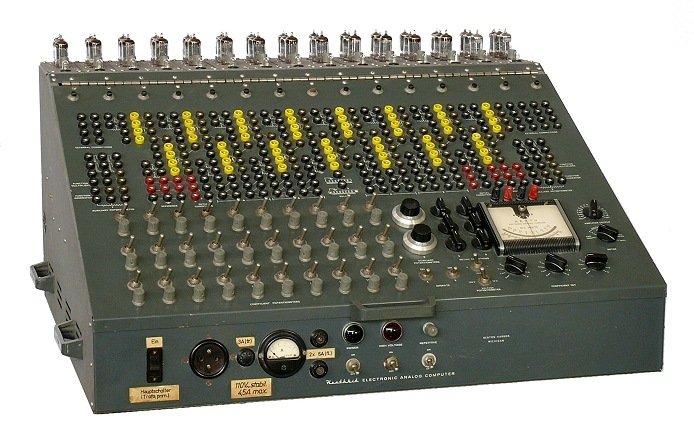
Figure 1.1 — The Heathkit ES-400 in its floor-standing cabinet. The 45 vacuum tubes of the fifteen ES-201 modules are visible across the top panel. The 364-jack patch field occupies the upper portion of the front panel; the 38 potentiometers and 52 switches occupy the lower sections.
1.5.2 Front panel layout
The front panel is a single large steel sheet with silk-screened labelling. It hinges forward from the top of the cabinet to allow access to the interior wiring harness — the hinge point is at the top, and the panel is heavy enough that the original kit instructions recommend installing locking tip-up support rods (the camper-shell type) before working inside.
The panel carries:
Table 7 — The panel carries
| Feature | Count | Notes |
|---|---|---|
| Banana-plug jacks | 364 | Accept 2 mm banana plugs; form the patch field |
| Potentiometers | 38 | 30 coefficient pots + 2 auxiliary 10-turn pots + meter/balance/IC pots |
| Switches | 52 | Mode switches (IC / Hold / Run), amplifier function switches, relay switches |
| Connectors | 14 | External I/O connectors for oscilloscope, recorder, and accessory connections |
| Front-panel meter | 1 | DC milliammeter for monitoring amplifier outputs |
| Dual bias diodes | 4 pairs | Used for function generation (breakpoint networks) |
| Operational relays | 2 | Electrically switchable during computation (for discontinuous functions) |
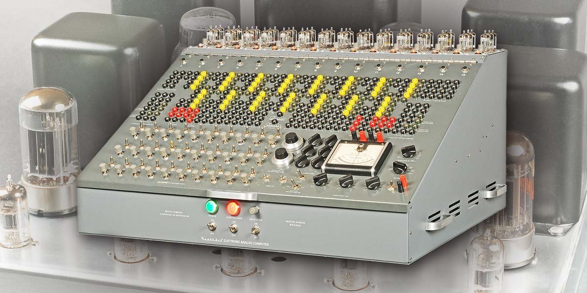
Figure 1.2 — ES-400 front panel after restoration by David Goodsell, 2019. The upper panel area is dominated by the 364-jack patch field; below it are the coefficient potentiometers and mode-select switches. The 45 tube crowns of the fifteen ES-201 modules are visible protruding above the panel. (Reference — courtesy Nuts & Volts / David Goodsell)
1.5.3 Interior — sub-assembly positions
Inside the cabinet, the sub-assemblies occupy specific bays:
  ES-400 INTERIOR LAYOUT (simplified top view)
  ┌─────────────────────────────────────────┐
  │  TOP PANEL — 15 × ES-201 tube crowns   │
  │  (3 tubes per module, 45 total)         │
  ├─────────────────────────────────────────┤
  │  [ES-201 × 15] — arranged in rows       │
  │  Each module is a self-contained PCB    │
  │  in sheet-metal housing                 │
  ├─────────────────────────────────────────┤
  │  [ES-2]       │  [ES-50] [ES-100 × 3]  │
  │  Amp PSU      │  [ES-151] [ES-505]      │
  │  (43 lb)      │  Reference & relay PSUs │
  ├─────────────────────────────────────────┤
  │  [ES-401] — bottom bay                 │
  │  Constant-voltage transformer, 250 VA  │
  └─────────────────────────────────────────┘
  Front panel hinges forward at top; 8 interior
  steel panels, originally unpainted (rust-prone)
The eight interior steel panels were not painted at the factory. Restoration typically involves sandblasting and powder-coating them in textured grey; the full procedure including powder-coat specification and star-lock washer grounding technique is in Vol 7.
Danger — Electrical ground in the ES-400 is completely isolated from chassis ground. This separation must be maintained through restoration. All ground connections must be made to the designated signal-ground bus, not to the chassis metalwork. Failure to observe this isolation creates DC offsets that propagate through every amplifier in the machine.
1.5.4 Tube complement — complete count
The ES-400 carries 73 vacuum tubes in total across all sub-assemblies. Of these, 45 are the active computing tubes of the fifteen ES-201 modules and are visible externally across the top panel. The remaining 28 are in the power supply sub-assemblies (ES-2, ES-50, ES-100, ES-151, ES-505).
Note — The source documents state 73 total tubes and 45 externally visible. The exact tube types and counts within each power supply sub-assembly are documented in the original Heath assembly manuals for those sub-assemblies. Vol 2 lists the complete PSU tube complement with values drawn from those manuals.
1.6 Decision Tree — Is the ES-400 the Right Machine?
The following decision tree assists a laboratory or collector in determining whether the ES-400 is an appropriate instrument for a given purpose, and which volume to consult first.
  START
    │
    ▼
  Are you a collector or historian?
    ├── YES → Vol 1 (this volume); see §3 for rarity and provenance.
    │          For acquisition strategy, see ES-400-Research.md §3.
    └── NO
          │
          ▼
        Are you restoring a unit you already own?
          ├── YES → Read Vol 2 FIRST (power safety).
          │          Then Vol 7 (restoration procedure).
          │          Then Vol 3 (ES-201 circuit).
          └── NO
                │
                ▼
              Do you need to solve differential equations
              with 8 or fewer simultaneous variables?
                ├── YES, and want to learn analog methods →
                │     Vol 5 (theory), then Vol 6 (programming).
                ├── YES, but have a fully working unit →
                │     Vol 4 (front panel), then Vol 6 (programming).
                └── NO / Need more variables →
                      The ES-400 with 15 op-amps supports
                      problems up to ~8th order (with summing
                      and inversion ops consuming some amps).
                      Consider whether problem scaling can
                      reduce order, or whether multiple passes
                      are acceptable. See Vol 5 §5.
1.7 Specifications Quick-Table
All values below are sourced from the Heath operational manual, the 1956 Heath brochure (CHM 102646297), and the Nuts & Volts restoration record. Values marked † are from the brochure; values marked ‡ are from the Goodsell restoration record; values marked § are from the Heath operational manual. Where a value is not available in the source documents, this is stated rather than estimated.
1.7.1 System-level specifications
Table 8 — System-level specifications
| Parameter | Value | Source |
|---|---|---|
| Manufacturer | Heath Company, Benton Harbor, Michigan | † |
| Full system designation | H-1 / ES-400 | † § |
| Production years | 1956–1962 | † § |
| Original price (Group C) | $945 | † |
| Estimated units produced | ~250–400 | ‡ (Penson) |
| Total weight, complete system | 168 lb | ‡ |
| ES-2 sub-assembly weight alone | ~43 lb | ‡ |
| Mains supply | 110 V / 60 Hz | † |
| Power consumption | ~450 W | § |
| Total vacuum tubes | 73 | § |
| Active computing tubes (visible) | 45 (ES-201 × 15 × 3) | § |
| Major sub-assemblies | 25 | § |
| Computing signal range | ±100 V DC | † § |
1.7.2 ES-201 operational amplifier specifications
Table 9 — ES-201 operational amplifier specifications
| Parameter | Value | Source |
|---|---|---|
| Open-loop DC gain | ~50,000 | § |
| Input voltage range | ±100 V | § |
| Output voltage range | ±100 V | § |
| Output current (max) | 10 mA | § |
| Integrator time constant (1 MΩ input, 1 µF feedback) | 1 second | § |
| Overload indicator | NE-51 neon lamp | § |
| Tubes per module | 3 (12AX7 + 6BQ7 + 6BH6) | † § |
| PCB substrate | Phenolic | ‡ |
1.7.3 ES-2 amplifier power supply outputs
Table 10 — ES-2 amplifier power supply outputs
| Rail | Voltage | Current (max) | Source |
|---|---|---|---|
| Positive HV | +250 V regulated | 250 mA | † |
| Negative HV | −250 V regulated | 250 mA | † |
| Grid-bias | −450 V regulated | 50 mA | † |
| Filament winding 1 | 6.3 VAC | 12 A | † |
| Filament winding 2 | 6.3 VAC | 2.5 A | † |
1.7.4 ES-50 reference supply
Table 11 — ES-50 reference supply
| Rail | Voltage | Source |
|---|---|---|
| Positive reference | +100 V regulated | † |
| Negative reference | −100 V regulated | † |
1.7.5 ES-100 initial condition supply
Table 12 — ES-100 initial condition supply
| Parameter | Value | Source |
|---|---|---|
| Output per module | 2 × 100 V floating | † |
| Number of ES-100 modules in Group C | 3 (= 6 floating IC supplies) | † |
1.7.6 ES-151 relay power supply
Table 13 — ES-151 relay power supply
| Output | Voltage | Source |
|---|---|---|
| Relay rails | 2 × 50 V | † |
1.7.7 ES-505 repetitive oscillator
Table 14 — ES-505 repetitive oscillator
| Parameter | Value | Source |
|---|---|---|
| Frequency range | 0.6–6 Hz | § |
| Function | Drives IC/Hold/Run cycle for repetitive display | § |
1.7.8 Front panel summary
Table 15 — Front panel summary
| Feature | Count | Source |
|---|---|---|
| Banana-plug jacks | 364 | § |
| Potentiometers (total) | 38 | § |
| — Coefficient pots | 30 | § |
| — Auxiliary 10-turn pots | 2 | § |
| Switches | 52 | § |
| External connectors | 14 | § |
| DC milliammeter | 1 | § |
| Dual bias diode sets | 4 | § |
| Operational relays | 2 | § |
1.7.9 ES-201 tube complement — full-system BOM extract
The table below gives the tube quantities required for all fifteen ES-201 modules in a complete Group C ES-400. Per-tube pricing is sourced from the Goodsell 2019 restoration record and reflects new-production availability at that time; current pricing should be verified against current supplier catalogues.
Table 16 — ES-201 tube complement — full-system BOM extract
| Tube type | Per module | × 15 modules | Notes | Approx. 2019 price (per tube) |
|---|---|---|---|---|
| 12AX7 | 1 | 15 | New Chinese production available | ~$9.59 (TubesAndMore.com) |
| 6BQ7 | 1 | 15 | Vintage / NOS preferred; TV-tuner type | Varies; eBay / NOS dealers |
| 6BH6 | 1 | 15 | Vintage / NOS; common IF amplifier type | Varies; eBay / NOS dealers |
| NE-51 | 1 | 15 | Neon indicator lamp; overload only | Widely available new |
Note — The 28 tubes in the power supply sub-assemblies (ES-2, ES-50, ES-100 × 3, ES-151, ES-505) are not listed here. Their types and counts are given in Vol 2, drawn from the 1956 Heath brochure and individual Heath assembly manuals for each sub-assembly.
1.8 Sources Cited in this Volume
-
Goodsell, David. “Restoring the Heathkit ES-400 Computer.” Nuts & Volts Magazine, 2019. nutsvolts.com/magazine/article/restoring-the-heathkit-es-400-computer
-
“Heath Electronic Analog Computer Kit.” Heath Company sales brochure, 1956. Computer History Museum brochure archive accession 102646297. s3data.computerhistory.org/brochures/heath.analog.1956.102646297.pdf
-
“H-1 Educational Computer.” Computer History Museum catalog, accession X799.86. computerhistory.org/collections/catalog/X799.86
-
Heath Company. Operational Manual — Heath Educational Analog Computer (ES-400 / H-1). Benton Harbor, Michigan: Heath Company, circa 1956–1962.
-
Penson, Chuck (WA7ZZE). Heathkit Test Equipment Products. Cited for production quantity estimate of 250–400 units.
-
“Electronic Analog Computer ES-400 Family.” RadioMuseum.org. radiomuseum.org/r/heath_electronic_analog_comput.html
-
“Heathkit ES-400.” Time-Line Computer Archive. t-lcarchive.org/heathkit-es-400/
Comments (0)