Heathkit ES-400 · Volume 4
Heathkit ES-400 — Volume 4 — Acquisition & restoration
Finding, inspecting, recapping, retubing, and bringing up a surviving ES-400 — companion to Vols 1–3 (architecture, programming, applications)
4.1 About this Volume
This volume addresses the practical end of ES-400 stewardship: finding a unit in the wild, evaluating what arrived, and executing a systematic restoration to working order. The ES-400’s rarity — an estimated 250–400 units manufactured between 1956 and 1962 — means that every surviving example is a non-renewable resource. Restoration decisions therefore carry historical weight as well as engineering consequence.
The primary documentary basis for this volume is David Goodsell’s eight-month restoration chronicled in Nuts & Volts magazine (2019), supplemented by the specifications established in the ES-400 and EC-1 operational manuals and the ES-201 service manual. Where Goodsell’s article provides specific product names, part numbers, or costs, those are cited directly. Where a value cannot be confirmed from available sources, this volume says so rather than interpolating.
Volume cross-references: Vol 1 covers system overview and history. Vol 2 covers hardware architecture and power supplies. Vol 3 covers computing elements and the patchbay. Vol 5 covers programming methodology.
4.1.1 System Overview Diagram
The diagram below shows the modular structure of the complete ES-400 system — which sub-assemblies supply what to which — as orientation before disassembly.
4.2 Finding a Rare ES-400 — the Sub-Assembly Hunt
4.2.1 The Naming Problem
Before beginning any search, the operator must understand the ES-400’s modular identity. “ES-400” refers only to the cabinet and front-panel chassis. The complete system — what Heath marketed as “Group C, Full Computer” at $945 original list price — is an assembly of separately model-numbered units that Heath sold and catalogued independently. Any one of them may surface without the others.
Table 1 — ES-400 sub-assembly model numbers and search terms
Table 1 — Table 1 — ES-400 sub-assembly model numbers and search terms
| Model | Description | Qty in Full System | Search Priority |
|---|---|---|---|
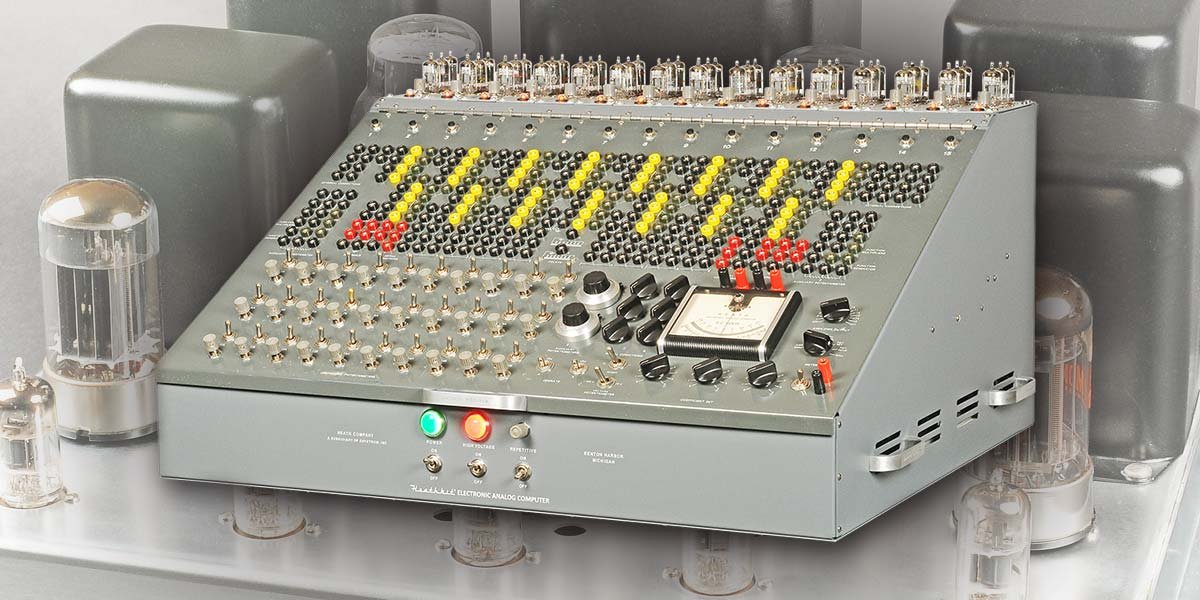
| ES-400 | Cabinet, front panel, 364 jacks, 38 pots, 52 switches, 14 connectors, 1 DC meter | 1 | Primary |
| ES-201 | DC Operational Amplifier (gain ~50,000; output ±100 V @ 10 mA) | 15 | Critical — often missing |
| ES-2 | Amplifier Power Supply (±250 V @ 250 mA, −450 V @ 50 mA, 6.3 VAC @ 12 A + 6.3 VAC @ 2.5 A) | 1 | Critical |
| ES-50 | Reference Power Supply (regulated ±100 V) | 1 | Critical |
| ES-100 | Initial Condition Power Supply (2× floating 100 V per unit) | 3 | Important |
| ES-151 | Relay Power Supply (2× 50 V) | 1 | Important |
| ES-505 | Repetitive Oscillator (0.6–6 Hz) | 1 | Useful |
| ES-600 | Function Generator (optional accessory) | 0 or 1 | Optional |
| ES-401 | Voltage Regulator Transformer (250 VA) | 1 | Critical |
Note — When posting a “Wanted” notice or setting up search alerts, include every model number from the table above. A seller listing “Heathkit ES-2” may not realise the unit is a component of the ES-400. Similarly, searching “heathkit ES-201” will surface individual amplifier modules sold off from parted-out systems.
4.2.2 Where Units Surface
eBay is the most productive single source. Save persistent searches for:
heathkit ES-400heathkit analog computerheath H-1 computerheathkit ES-201heathkit ES-2 power supply
Sort by “newly listed” and check weekly. Accessories and documentation sometimes appear first and can lead to the unit owner.
Vintage Computer Federation (VCF) Forums marketplace (forum.vcfed.org) is the primary collector community. A “Wanted” post costs nothing. A past listing for an ES-400 front panel appeared there (item 57596); that sale history at least confirms units do occasionally circulate.
Antique Radio Forums (antiqueradios.com) carries active Heathkit discussion threads. Posting in the “Wanted” section reaches engineers and ham operators who often acquired ES-400 units through institutional surplus.
Heath mailing list archive (puck.nether.net/pipermail/heath/) and the SEBHC Google Group ([email protected]) are smaller but targeted communities. A polite enquiry there may reach the right person.
WorthPoint (worthpoint.com) provides historical auction records useful for establishing realistic price expectations before bidding.
4.2.3 Museums as Leads
Several institutions hold confirmed ES-400 or related units. They do not sell collection pieces, but curators sometimes know of private owners or duplicate holdings:
Table 2 — Known institutional ES-400 locations
Table 2 — Table 2 — Known institutional ES-400 locations
| Institution | Location | Status | Contact |
|---|---|---|---|
| Computer History Museum | Mountain View, CA | H-1 / ES-400, catalog X799.86, acquired 1987 | computerhistory.org |
| Technikum29 | Frankfurt, Germany | ES-400 on display (loan from FITG) | technikum29.de |
| Time-Line Computer Archive | United Kingdom | Front panel only (incomplete) | t-lcarchive.org |
| System Source Computer Museum | Hunt Valley, MD | Heathkit EC-1 (smaller model) | museum.syssrc.com |
| The Computer Church | Parkesburg, PA | Early computer collection | thecomputerchurch.org |
4.2.4 Acquisition Realism
Units appear on the open market only a few times per decade. Goodsell, whose restoration is the basis of this volume, acquired his unit in Southern California — he found it roughly halfway through a search process and noted the ES-400 was not including its tubes when acquired. The realistic acquisition picture:
- Patience: Budget 1–3 years of active searching before assuming the market is dry.
- Flexibility: An incomplete unit — even a bare front panel or a set of ES-201 modules — is a starting point worth acquiring.
- Estate and surplus channels: Many original owners were industrial or university engineers who have since passed. Estate sales, storage unit auctions, and university surplus (particularly physics and engineering departments) are productive channels.
- Freight budget: At 168 lbs for the complete system, domestic freight runs $200–$500. Obtain freight quotes before committing to a distant purchase.
- Price anchor: The original 1956 list price was $945, equivalent to approximately $8,175 in 2019 dollars. Condition, completeness, and provenance dominate current market pricing; no reliable recent sale data exists for a complete system. Individual ES-201 modules occasionally appear for $50–$200 each depending on condition.
(reference — courtesy Nuts & Volts / David Goodsell)
4.3 Inspection Checklist
Upon receipt, before any power is applied, the following systematic inspection establishes baseline condition and drives the restoration plan.
Danger — The ES-2 amplifier power supply develops ±250 V DC and −450 V DC on internal nodes. Large-value electrolytic capacitors in a machine that has sat for decades may hold charge for extended periods after the last power application. Never assume capacitors are discharged. Use a high-voltage bleeder resistor (100 kΩ, 5 W minimum) across each supply output before touching internal components, and verify discharge with a properly rated meter.
4.3.1 Physical and Cosmetic Inspection
Table 3 — Arrival inspection checklist
Table 3 — Table 3 — Arrival inspection checklist
| Item | Check | Common finding |
|---|---|---|
| Front panel silk-screening | Examine under raking light for scratches, missing labels | Some panels lack ON/OFF markings; labels often taped over |
| Front panel finish | Look for corrosion, tape residue, paint lifting | Tape residue common; panel itself usually survives well |
| Cabinet exterior | Check for rust, dents, paint peeling | Mild surface rust typical; interior panels fare worse |
| Interior steel panels (8 total) | Inspect for rust penetration | Often heavily rusted; powder-coat remediation usually required |
| Banana jacks (364 total) | Check for cracked or stripped bodies | Individual jacks replaceable; count missing/damaged |
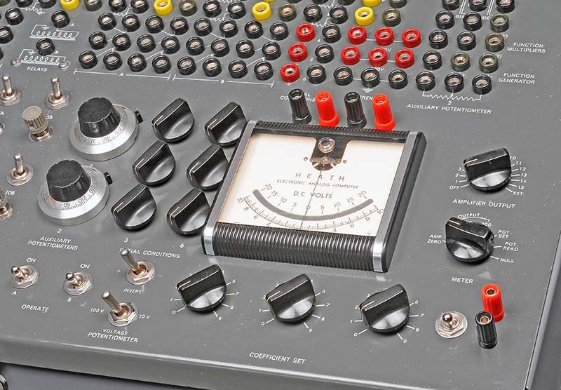
| Potentiometers (38 total) | Rotate each — note scratchy or open pots | Carbon track wear expected after decades |
| Switches (52 total) | Operate each — note intermittent contacts | Oxidized contacts; DeoxIT often sufficient |
| Front panel meter | Inspect pointer and zero | Often undamaged; check for seized movement |
| Knobs | Count against expected complement | Daca-Ware knobs frequently missing; source from vintage Heathkit MM-1 VOM |
| Patch cord set | Count and condition | Almost always missing entirely |
4.3.2 Sub-Assembly Inventory
Document which model-numbered assemblies are present using Table 1. Photograph each assembly from multiple angles before disconnecting anything. Note serial numbers if legible. The ES-201 modules are the most commonly missing items — units sold as “complete” sometimes have fewer than 15 installed.
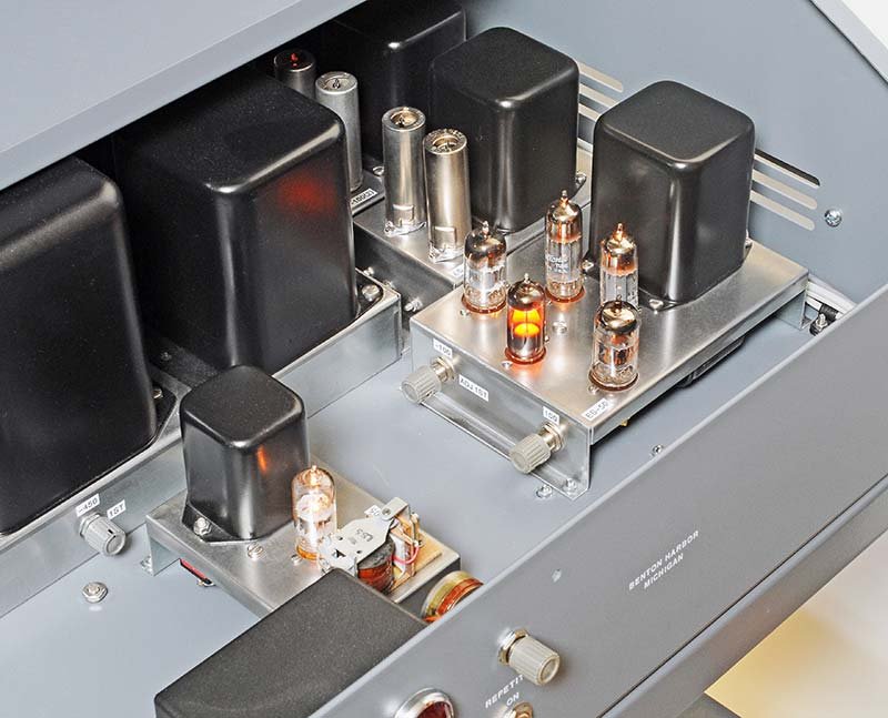
4.3.3 Transformer and Inductor Inspection
The ES-2 supply contains multiple transformers and filter chokes. Inspect each for:
- Rust on the lamination stack
- Charring or melted insulation on the windings
- Cracked or disintegrated potting compound
A transformer showing winding damage is not necessarily failed — Goodsell’s unit had rusty transformers that cleaned up and performed correctly after refinishing. Disassemble the supply, clean laminations, apply two coats of primer followed by satin black spray paint, and reassemble.
4.3.4 Capacitor Assessment
Do not attempt to reform vintage electrolytics in an ES-400. Given the high rail voltages (up to 350 V), a leaky or shorted capacitor can cause catastrophic failures elsewhere. The correct approach is blanket replacement of all electrolytic and paper/wax capacitors throughout the system. Mica and ceramic caps may be left in place if they test within tolerance.
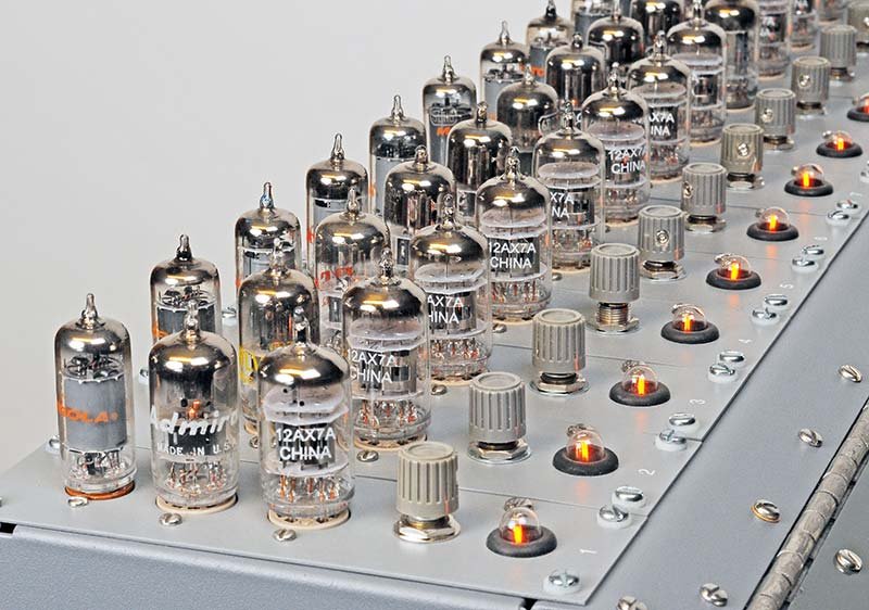
4.3.5 Tube Inventory
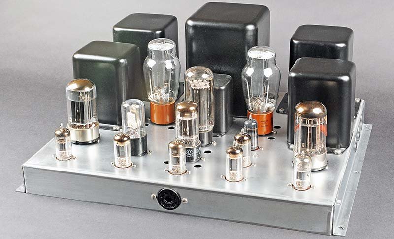
The complete ES-400 requires exactly 45 active tubes in the 15 ES-201 modules (3 per module: one 12AX7, one 6BQ7, one 6BH6) plus tubes in the power supplies and ES-505 oscillator — 73 tubes total. Count what is present. Expect the active tube complement to be largely absent: tubes are the easiest items to remove and sell individually, and many ES-400 units were stripped before storage.
4.3.6 Ground Isolation Verification
The ES-400 design intentionally isolates electrical signal ground (the computer’s reference) from chassis ground (the steel enclosure). This is not a fault — it is by design. Verify with an ohmmeter that no low-resistance path exists between the two grounds before any other work proceeds. Damage to this isolation boundary introduces noise that defeats the machine’s accuracy.
Note — Star-lock washers must be used under every panel mounting screw when reassembling powder-coated interior panels. Powder coat is electrically insulating; without the washers cutting through the coating, the panel is not bonded to chassis ground.
(reference — courtesy Nuts & Volts / David Goodsell)
(reference — courtesy Nuts & Volts / David Goodsell)
4.4 Recapping — Full BOM with Modern Replacements
Recapping is the single highest-impact restoration step. Every electrolytic and paper/film capacitor in the system should be replaced regardless of measured leakage, because vintage electrolytics that test acceptable at room temperature on a bridge may fail catastrophically under load at rated voltage.
4.4.1 ES-2 Amplifier Power Supply Capacitors
The ES-2 contains 16 large axial electrolytic capacitors ranging from 20 µF at 350 V to 70 µF at 350 V. Goodsell sourced these from TubesAndMore.com (Antique Electronic Supply). In addition to the large filter caps, replace all smaller electrolytics and all wax-paper or paper-in-oil capacitors.
Danger — The ES-2 develops up to −450 V DC on the bias supply node. Capacitors used across this rail must be rated for at least 500 V, preferably 525 V. Do not substitute a 350 V-rated device in a 450 V position. Verify the polarity of every electrolytic before soldering — reversed polarity at these voltages is catastrophic.
The following notes on replacement selection apply specifically to the ES-2 high-voltage environment:
- Axial vs. radial: The original ES-2 layout uses axial-lead electrolytics in through-board and terminal-strip mounting positions. Modern high-value / high-voltage electrolytics are predominantly radial-lead. When substituting radial-lead devices in axial positions, fabricate a short adapter from stiff tinned-copper wire to bring both leads to the original mounting holes. Ensure the radial body does not contact adjacent components or the chassis.
- Voltage derating: Always apply a minimum 20% voltage derating in high-temperature environments. The ES-2 interior reaches 50–60°C with the supply running. A position nominally at 350 V should use a 450 V or 500 V rated cap. A position nominally at 450 V should use 550 V or 600 V.
- Ripple current: The ES-2 filter caps carry substantial ripple current (the ES-2 supplies ±250 V at 250 mA each rail). Select modern replacements with ripple current ratings at least matching the original specification; 105°C-rated series from Illinois Capacitor, Cornell Dubilier, or Nichicon provide appropriate margins.
- Reforming new-old-stock caps: The guidance here applies to vintage original capacitors, not to new-production replacements. New-production electrolytics require no reforming — install and use.
Wax-paper and paper-in-oil capacitors in the ES-2 bias network and filter positions must be replaced unconditionally. These dielectric types absorb moisture over decades, become leaky, and in high-voltage positions can fail short — potentially destroying other components. Replace with polyester film types of equal or greater voltage rating.
4.4.2 ES-201 Operational Amplifier Capacitors
Each of the 15 ES-201 modules carries a phenolic PCB with resistors and capacitors. The Goodsell restoration replaced every capacitor on every board. Specific values for the bouncing-ball demonstration patch are documented in the Nuts & Volts parts list (Table 4 below draws on the article’s published BOM).
Table 4 — ES-201 / Patch BOM with modern replacement part numbers
Table 4 — Table 4 — ES-201 / Patch BOM with modern replacement part numbers
| Designator | Value / Rating | Function | Modern Replacement | Supplier | Approx. Unit Cost |
|---|---|---|---|---|---|
| C1, C2, C3, C5 | 1 µF / 630 V | Integrator timing capacitors | C-FS-630-1MFD (Antique Electronic Supply) | TubesAndMore.com | ~$4.50 ea |
| C4 | 0.1 µF / 50 V | Bypass / coupling | 399-4151-ND (film, 0.1 µF 50 V) | Digi-Key | ~$0.40 ea |
| ES-2 filter caps (large) | 20–70 µF / 350–500 V axial | B+ filter | Sprague Atom series or Illinois Capacitor axial electrolytics at appropriate µF / 500 V | TubesAndMore.com / Mouser | $3–$12 ea |
| ES-2 filter caps (small) | 1–10 µF / 350 V | Regulator bypass | Nichicon UVZ series, 105°C rated | Mouser | $0.50–$2 ea |
| Paper/wax bypass caps (all assemblies) | Various, typically 0.01–0.1 µF | Bypass / decoupling | Vishay / Kemet polyester film, same µF, 400 V minimum | Mouser / Digi-Key | $0.20–$1 ea |
Note — The ES-201 phenolic PCBs are fragile. Goodsell noted that two pads lifted per board on average during desoldering. Work with a temperature-controlled iron at the lowest effective temperature, use solder wick rather than a solder sucker, and support the board firmly. Repair lifted pads with fine gauge (30 AWG) hookup wire rather than attempting to re-bond the pad to the substrate.
4.4.3 ES-100 Initial Condition Supply Capacitors
Three ES-100 units provide six independent floating 100 V supplies for initial condition setting. Apply the same procedure as the ES-2: replace all electrolytics and paper caps. The ES-100 rails are lower voltage than the ES-2 (100 V maximum), but the capacitors are equally aged and equally suspect.
4.4.4 ES-151 Relay Supply Capacitors
The ES-151 provides 2× 50 V for the two operational relays. Straightforward recapping — same methodology, lower voltage stress.
4.4.5 ES-505 Repetitive Oscillator Capacitors
The ES-505 oscillator frequency is set by an RC network. Timing capacitors here are particularly important: value drift in aged capacitors shifts the oscillator frequency away from the nominal 0.6–6 Hz range. Replace timing capacitors with 1% film types to maintain calibration.
4.4.6 Resistor Replacement in ES-201 Modules
The ES-201 uses 1% precision resistors (originally metal-film or wirewound types) and carbon-composition types for less critical positions. Goodsell measured all resistors before discarding them and found the 1% types were often still within specification, but he replaced them anyway because copper-oxide corrosion on the metal end-caps creates intermittent contact resistance not captured by a static DC measurement. Replace with 1% metal-film resistors throughout.
Table 5 — ES-201 resistor BOM (patch components per Goodsell/Nuts & Volts)
Table 5 — Table 5 — ES-201 resistor BOM (patch components per Goodsell/Nuts & Volts)
| Designator | Value | Wattage | Digi-Key Part | Notes |
|---|---|---|---|---|
| R1, R3, R4, R8, R12, R14, R21, R23–R25 | 1 MΩ | 1/2 W | 1.0MH-ND | Input / feedback resistors |
| R2 | 200 kΩ | 1/2 W | 200KH-ND | |
| R5, R6, R10 | 10 MΩ | 1/2 W | 10MH-ND | High-value summing |
| R7, R22 | 2 MΩ | 1/2 W | 2.0MH-ND | |
| R9 | 5 MΩ | 1/2 W | 5.0MH-ND | |
| R11 | 20 kΩ | 1/2 W | 20KH-ND | |
| R13 | 500 kΩ | 1/2 W | 510KH-ND | |
| R15, R16, R18 | 10 kΩ | 1/2 W | 10KH-ND | |
| R20 | 100 kΩ | 1/2 W | 100KH-ND | |
| R17, R19 | 25 kΩ pot | — | R-V38-25KL (Antique Electronic Supply) | Balance / gain trim |
All Digi-Key numbers are from the Goodsell Nuts & Volts article published c. 2019 — verify current stock before ordering.
4.4.7 Tube Sockets
Replace all 45 tube sockets in the ES-201 modules (3 per module). The original phenolic sockets develop contact resistance and intermittent grip. Use:
- 9-pin noval sockets for the 12AX7 and 6BQ7 (source: Mouser, Digi-Key, or TubesAndMore.com)
- 7-pin miniature sockets for the 6BH6
Prefer sockets with gold-flashed or silver-flashed contacts over unplated brass in computing applications, where contact resistance directly contributes to input offset error.
4.4.8 Procurement Cost Summary
The table below aggregates the materials cost of a complete ES-400 restoration based on the Goodsell restoration (2019 pricing). Current pricing from Mouser and Digi-Key may differ.
Table 10 — Restoration cost summary
Table 6 — Table 10 — Restoration cost summary
| Category | Items | Estimated Cost (2019 basis) | Notes |
|---|---|---|---|
| Active tubes — 12AX7 × 15 | New production, Chinese | ~$144 | $9.59 ea from TubesAndMore.com |
| Active tubes — 6BQ7 × 15 | Vintage NOS | ~$90–$150 | eBay pricing varies widely |
| Active tubes — 6BH6 × 15 | Vintage NOS | ~$60–$120 | eBay pricing varies |
| NE-51 neon lamps × 20 (spares) | New production | ~$10 | Mouser / Digi-Key |
| Tube sockets (9-pin noval × 30, 7-pin × 15) | New | ~$40–$80 | Mouser / Digi-Key |
| ES-2 large electrolytic caps × 16 | New, 450–500 V rated | ~$80–$150 | TubesAndMore.com / Mouser |
| ES-2 small electrolytics + film caps | Various | ~$40–$80 | Mouser / Digi-Key |
| ES-201 capacitors × 15 modules | 1 µF 630 V film + others | ~$120–$200 | TubesAndMore.com (C-FS-630-1MFD) |
| ES-201 resistors × 15 modules (all values) | 1% metal film | ~$30–$60 | Mouser / Digi-Key |
| ES-50, ES-100 (×3), ES-151 caps | Various | ~$40–$80 | Mouser |
| Interior panel powder-coating (8 panels) | Professional shop | ~$180 | Goodsell direct cost |
| Custom dry-transfer labels | CustomRubOnTransfers.com | ~$65 | If missing labels |
| Meguiar’s Ultimate Compound + Cleaner Wax | Auto parts store | ~$30 | Front panel cleaning |
| Spray paint (satin black + primer, transformer cans) | Hardware store | ~$20 | |
| Star-lock washers (assorted) | Hardware store | ~$10 | Panel grounding — not optional |
| Locking tip-up support rods × 2 | RV / hardware store | ~$40 | Front panel support during service |
| Patch cords (banana plug, assorted) | eBay / electronics | ~$50–$100 | 2 mm banana; 35+ cords for demos |
| Total materials (approximate) | ~$1,000–$1,500 | Excluding tools and shipping |
This figure does not include the cost of the unit itself (undefined — no open-market reference), tools (oscilloscope, Variac, tube tester, meter), or shop labour for powder-coating and sandblasting if not performed in-house.
4.5 Tubes — Complement, Testing, Sourcing, Substitutions
4.5.1 ES-201 Amplifier Signal-Flow Diagram
The diagram below traces the three-stage signal path through one ES-201 module and illustrates the feedback topology that defines its computing function. The open-loop gain of approximately 50,000 forces the summing junction (Σ) to remain at virtual ground in all closed-loop configurations.
Reading the diagram: Plug-in input resistors (R_in) at each input jack set the gain weight for that input at the summing junction. The three amplifier stages develop an open-loop gain of approximately 50,000, making the summing junction a virtual ground in any closed-loop configuration. The feedback impedance (Z_fb) determines the computing function: a resistor produces a weighted summer (gain = −R_fb/R_in); a capacitor produces an integrator (output = −(1/R_in·C_fb)∫V_in dt). The NE-51 neon lamp fires when the output approaches ±100 V, providing visible overload indication. See Vol 2 for complete ES-201 circuit analysis.
4.5.2 Complete Tube Complement
The ES-400 requires 73 vacuum tubes in total across all assemblies. The dominant consumer is the ES-201 array.
Table 6 — Full ES-400 tube complement
Table 7 — Table 6 — Full ES-400 tube complement
| Assembly | Tube Type | Qty per Assembly | Total Qty | Function |
|---|---|---|---|---|
| ES-201 (×15) | 12AX7 | 1 | 15 | High-gain input triode stage |
| ES-201 (×15) | 6BQ7 | 1 | 15 | Intermediate triode stage (TV-tuner type) |
| ES-201 (×15) | 6BH6 | 1 | 15 | Sharp-cutoff pentode output / buffer stage |
| ES-201 (×15) | NE-51 neon lamp | 1 | 15 | Overload / saturation indicator |
| ES-2, ES-50, ES-100 (×3), ES-151 | Rectifier / regulator types | Per schematic | ~28 | Power supply regulation and rectification |
| ES-505 | Per schematic | Per schematic | Per schematic | Repetitive oscillator |
The 45 tubes in the ES-201 modules (12AX7 + 6BQ7 + 6BH6 × 15 each) are the tubes visible externally across the top of the cabinet. Power supply tube types are specified in the ES-2 and ES-50 service manuals — not independently confirmed here; consult the original manuals.
4.5.3 Testing
Test all recovered tubes before committing to a tube purchase. A mutual-conductance tester (e.g., Hickok 539, 752, or equivalent) provides the most meaningful results for linear amplifier tubes. Emission testers are a second-best option. Minimum acceptance thresholds:
- 12AX7: Gm should exceed 1,600 µmhos per section; both sections of each tube should track within ~10% for lowest offset contribution in the ES-201 differential input stage.
- 6BQ7: Intermediate TV-tuner triode; test both sections; any tube showing significant grid current should be rejected.
- 6BH6: Pentode; Gm should be consistent across all 15 tubes; low Gm units cause gain shortfall and difficulty balancing.
4.5.4 Sourcing
12AX7 / ECC83 — The most common small-signal audio tube in the world. New-production tubes are manufactured in China, Russia (Sovtek, Electro-Harmonix), Slovakia (JJ), and Serbia (Ei). Goodsell sourced Chinese new-production units from TubesAndMore.com at approximately $9.59 each and reported satisfactory results. Avoid premium “matched pair” listings aimed at audiophiles — the premium is not warranted for a computing application, and the markup is substantial.
6BQ7 / 6BZ7 / ECC180 — TV-tuner triode, less commonly stocked. Seek vintage NOS (new-old-stock) from eBay tube dealers. The 6BZ7 is a close variant (higher transconductance) and will substitute in the ES-201 circuit. Confirm pinout compatibility before installation.
6BH6 / EF94 — Sharp-cutoff pentode; a standard IF amplifier tube from the late 1950s, reasonably available as NOS stock. No new-production equivalent is currently manufactured.
NE-51 neon indicator lamps — Available new from general electronics suppliers (Mouser, Digi-Key). The NE-51 requires a series resistor to set operating current; verify the original circuit value (typically 47 kΩ–100 kΩ) before substituting. One NE-51 failed in Goodsell’s restoration.
Table 7 — Tube sourcing summary
Table 8 — Table 7 — Tube sourcing summary
| Tube | Status | Primary Source | Notes |
|---|---|---|---|
| 12AX7 | New production available | TubesAndMore.com | ~$9.59 ea (2019 pricing); current pricing TBD |
| 6BQ7 | NOS only | eBay, specialty tube dealers | 6BZ7 substitutes (higher Gm — verify circuit) |
| 6BH6 / EF94 | NOS only | eBay, specialty tube dealers | Common IF tube; adequate supply as of 2019 |
| NE-51 | New production available | Mouser, Digi-Key, any electronics distributor | Check series resistor value in circuit |
4.5.5 Substitution Notes
The ES-201 gain structure provides very high open-loop gain (~50,000). The exact tube types matter less than the requirement that all 15 amplifiers track well after balancing. If a direct substitute must be used in the 6BQ7 position, confirm with the ES-201 schematic that the operating point (plate voltage, cathode resistor, screen voltage) is compatible with the substitute’s characteristic curves. Do not substitute without schematic verification.
4.6 Cabinet Refinishing
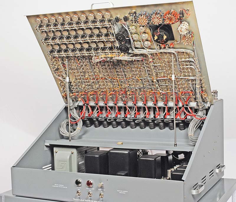
4.6.1 Front Panel Access — the Hinge and Safety Problem
Before any front panel work begins, the operator must address the front panel’s mechanical support. The ES-400 panel is extremely heavy — all 364 banana jacks, 38 potentiometers, 52 switches, and their associated hardware are mounted here. The original equipment provided only a wooden stick for support.
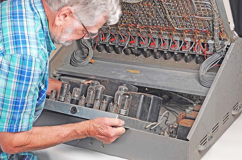
Danger — The front panel opens on a lower hinge and leans forward. Unsupported, it will fall, potentially injuring anyone in its path and destroying the silk-screened surface on contact with the floor. Install locking tip-up support rods — the type used for truck camper shells — before reaching inside. Goodsell fabricated a pair of these supports and attached them to the chassis permanently for repeated safe access during the restoration. Two rods are better than one; the panel must be locked, not merely propped.
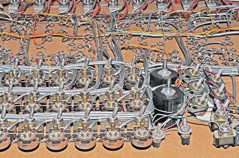
The wiring harness removal technique substantially reduces risk during teardown. Rather than unsoldering or cutting hundreds of individual wires, the entire front-panel wiring harness can be removed as a single unit by unscrewing all 364 banana jacks from the rear of the panel while leaving wires attached. This preserves all wire-to-jack assignments and makes reassembly straightforward: reinstall the jacks in their labeled positions and the wiring topology is automatically restored.
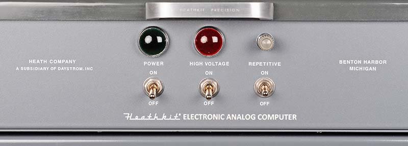
The ES-400 front panel is steel with silk-screened lettering applied over a painted surface. Silk-screening is not recoverable once damaged — the restoration goal is preservation, not replacement.
Cleaning and refinishing procedure (per Goodsell):
- Remove masking tape residue by hand — thumbnails are preferable to any tool that might scratch the surface.
- For stubborn adhesive, test 409, Citrus Magic, or Goo Gone in an inconspicuous area. Some solvents attack the underlying paint.
- Clean the entire panel with Meguiar’s Ultimate Compound applied vigorously with a soft cloth.
- Follow with two coats of Meguiar’s Cleaner Wax.
- Do not sand. Do not use abrasive pads. Do not use lacquer thinner or acetone.
Missing or damaged silk-screening: If labels are absent or damaged beyond cosmetic cleaning, source a custom dry-transfer (rub-down) sheet from CustomRubOnTransfers.com — approximately $65 per sheet. Match the font and size to surviving labels on the panel. The result, while less durable than original silk-screening, is visually convincing. Apply a clear-coat overspray after the transfers have cured to improve scratch resistance.
Note — Some ES-400 units have no ON/OFF labeling on the power section. Goodsell confirmed this is an original production variant, not a previous modification. Recreating the missing labels with dry transfers is correct practice.
(reference — courtesy Nuts & Volts / David Goodsell)
(reference — courtesy Nuts & Volts / David Goodsell)
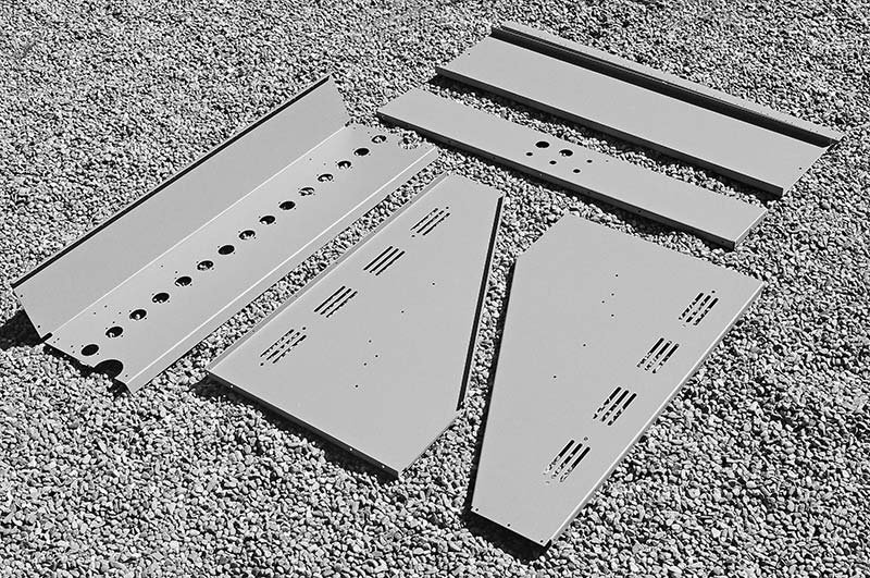
4.6.2 Interior Steel Panels (8 panels)
The eight interior steel panels were not painted in the original production; they were left bare steel. After decades, they are typically heavily rusted.
Recommended procedure:
- Remove all panels from the cabinet.
- Have them sandblasted at a local shop to remove rust.
- Have them powder-coated inside and out in textured gray. Goodsell paid approximately $180 for all eight panels.
- During reassembly, use star-lock washers under every mounting screw to cut through the powder coat and establish chassis ground continuity. Powder coat is electrically insulating — this step is not optional.
4.6.3 Transformer Cans and Chokes
Disassemble the ES-2 supply completely. Clean all transformer lamination stacks and choke cores with a wire brush. Apply two coats of gray metal primer, then two coats of satin black spray paint. Reassemble. This step is cosmetic but also protects against further corrosion that could eventually compromise the transformer.
4.6.4 Knobs
The ES-400 uses distinctive Daca-Ware knobs. These are not commonly available as new-old-stock. The most reliable source is vintage Heathkit MM-1 VOM multimeters on eBay, which use the same knob style and can be parted out; individual knobs run approximately $3–$20 depending on size and seller. Inspect all knobs for cracked skirts or stripped set-screw holes before installation.
4.7 Bring-Up and Amplifier Balancing
This section covers the ordered power-up and calibration sequence after all mechanical and component-level restoration is complete. No power should be applied at any stage until the preceding stage has been verified.
ES-400 BRING-UP SEQUENCE
═══════════════════════════════════════════════════════════════════

  STAGE 1          STAGE 2          STAGE 3          STAGE 4
  ─────────        ─────────        ─────────        ─────────
  ES-2 power  →   Auxiliary    →   ES-201 op-   →   System
  supply          supplies         amp balance      verification
  verification    (ES-50,          (all 15 units)
                  ES-100,
                  ES-151)

  Check:          Check:           Procedure:       Check:
  ±250 V DC       ±100 V DC ref    Short input,     Simple
  −450 V DC       6× 100 V IC      adjust balance   integrator
  6.3 VAC         2× 50 V relay    pot to zero      test circuit
  regulated       supplies         output           see §8
4.7.1 Stage 1 — ES-2 Amplifier Power Supply
Danger — The ES-2 develops −450 V DC on the bias supply rail. This voltage is lethal. Keep one hand behind the back when probing live circuits. Use insulated test leads rated for 1 kV minimum. Do not work alone.
- Before applying mains power, verify with an ohmmeter that no short exists between any supply output terminal and chassis ground.
- If a Variac (autotransformer) is available, bring mains voltage up slowly from zero over 5–10 minutes while monitoring outputs. This stresses reforming capacitors gently and reveals any remaining leakage.
- At full mains voltage, measure and record each output: +250 V DC, −250 V DC, −450 V DC, and 6.3 VAC heater. Compare to specification.
- Allow a 30-minute soak at full voltage and re-measure. Thermal drift in restored capacitors is normal; the outputs should stabilise.
- Do not connect the ES-2 to the rest of the system until outputs are within ±5% of specification and stable.
Danger — The ES-2 weighs approximately 43 lbs. Use a helper or a shop lift when removing or reinstalling it in the cabinet. The high voltages present even immediately after switch-off make dropping this assembly a particularly hazardous event.
4.7.2 Stage 2 — Auxiliary Supplies
Apply the same verification procedure to the ES-50 (reference supply, ±100 V), each ES-100 (initial condition supplies, 100 V floating per winding), and ES-151 (relay supply, 2× 50 V). Verify isolation between each ES-100 floating supply and chassis ground — these supplies must remain floating for the initial condition system to function correctly.
4.7.3 Stage 3 — ES-201 Operational Amplifier Balancing
With all power supplies verified, install the ES-201 modules and connect them to the ES-2 heater and plate supply. Allow a 15-minute warm-up period before balancing — tube operating points shift substantially during the first several minutes of heater warm-up.
Balance procedure (from operational manual):
FOR EACH OF THE 15 ES-201 MODULES:

  1. Remove all plug-in resistors and capacitors from
     the module's input and feedback jacks.
  2. Connect the module's output to the front-panel
     AMPLIFIER OUTPUT jack via the front-panel
     selector switch.
  3. Connect the front-panel DC milliammeter to read
     output voltage (via the meter switch).
  4. Short the module's summing junction to electrical
     ground.
  5. Adjust the BALANCE potentiometer for that module
     until the meter reads zero (null).
  6. Remove the summing junction short.
  7. Record the balance pot setting for future reference.

  Repeat for all 15 modules.
Note — Balance will drift over time as tubes age and warm up. The procedure should be repeated at the start of any extended computing session, and again any time a tube is replaced. A well-balanced amplifier holds null to within ±0.1 V on the output; anything worse than ±1 V indicates a tube problem or a resistor value issue in the feedback network.
4.7.4 Stage 4 — System Verification
Once all 15 amplifiers balance satisfactorily, perform a simple integrator test. The diagram below shows the patch configuration for the integrator smoke test, which exercises the ES-2 plate supply, the ES-50 reference supply, and one ES-201 module simultaneously.
Verify that the ramp is linear (not curved or stepped), that the output reaches the expected voltage at the expected time, and that the IC reset returns the output cleanly to zero. Any deviation from linear behaviour indicates a leaky capacitor or an out-of-specification resistor.
Quantitative check: With R_in = 1 MΩ and C_fb = 1 µF, the integration time constant τ = RC = 1 second. With the coefficient pot set to 0.05 of +100 V (i.e., +5 V at the pot wiper), the integrator input voltage is +5 V. The output ramp rate is −V_in / τ = −5 V/s. At 10 seconds the output should read −50 V. This calculation is independent of tube gain — the high open-loop gain makes it so. A ramp that does not obey this relation to within ±5% indicates a component problem, not a calibration issue.
Harmonic oscillator check (two-amplifier test): After the single-integrator test passes on all 15 modules, connect any two verified integrators in a closed loop (output of integrator 2 fed through a coefficient pot back to the input of integrator 1). This produces a continuous sine-wave oscillation. The frequency should equal ω/(2π) where ω = √(k_pot / τ²) with τ = 1 s. Setting the pot to 0.01 gives ω ≈ 0.1 rad/s, or about 0.016 Hz — a cycle every ~63 seconds, observable on the panel meter. Setting the pot to 1.0 gives ω = 1 rad/s (0.159 Hz), more conveniently displayed on an oscilloscope. A clean sustained sinusoid with stable amplitude confirms both integrators are balanced and their capacitors are within specification. See Vol 3 for the full harmonic oscillator patch derivation.
(reference — courtesy Nuts & Volts / David Goodsell)
(reference — courtesy Nuts & Volts / David Goodsell)
(reference — courtesy Nuts & Volts / David Goodsell)
4.8 Troubleshooting Triage
The following table organises the most likely failure modes by symptom, with the probable cause ranked by frequency of occurrence and the recommended diagnostic path.
Table 8 — Troubleshooting triage
Table 9 — Table 8 — Troubleshooting triage
| Symptom | Most Probable Cause | Secondary Cause | Diagnostic Step | Resolution |
|---|---|---|---|---|
| ES-2 supply output incorrect or absent | Shorted or open electrolytic capacitor | Open rectifier tube or failed selenium rectifier | Measure each filter cap ESR; check rectifier continuity | Replace failed caps; replace rectifier (modern Si diode + series resistor to match voltage drop) |
| ES-2 output unstable / oscillating | Defective regulator tube | Open bypass capacitor on regulator grid | Substitute regulator tube; check bypass cap | Replace tube; replace cap |
| One ES-201 cannot balance (drifts) | Defective 12AX7 (one section weak or shorted grid) | Open cathode resistor or lifted PCB trace | Substitute known-good 12AX7; check resistors in-circuit | Replace tube or repair trace |
| ES-201 output saturated positive | Input summing junction connected to positive rail via leaky coupling cap | Defective 6BH6 (high plate current) | Remove all input components — check if output releases; substitute 6BH6 | Replace leaky coupling cap or tube |
| ES-201 output saturated negative | Leaky coupling cap pulling input negative | Defective 6BQ7 (asymmetric section) | Same as above; substitute 6BQ7 | Replace cap or tube |
| NE-51 indicator on continuously with no overload | NE-51 firing voltage has dropped (aged tube) | Threshold-setting resistor changed value | Measure firing voltage across NE-51; compare to circuit design | Replace NE-51 |
| Integrator ramp is non-linear (curved) | Leaky feedback capacitor (dielectric absorption) | Input resistor out of tolerance | Swap feedback capacitor with known-good 1 µF / 630 V film cap | Replace capacitor |
| Integrator ramp runs in wrong direction | Feedback capacitor polarity reversed (electrolytic) | Wrong tube configuration (amplifier wired as summer) | Check capacitor polarity marking against circuit; verify patch | Reverse capacitor; check patch |
| Potentiometer scratchy / intermittent | Oxidised resistive track | Worn wiper | Apply DeoxIT D5 sparingly through adjustment shaft opening; exercise | If no improvement, replace pot with equivalent value |
| ES-100 IC supply output wrong | Failed filter cap | Open series resistor in regulator | Measure cap in-circuit; check series resistor continuity | Replace failed component |
| ES-505 oscillator frequency incorrect | Aged timing capacitor (value shifted) | Oxidised trimmer pot contact | Replace timing capacitors with 1% film types; check trimmer | Replace caps; clean trimmer |
| Relay chatters or fails to pull in | ES-151 supply output low | Relay coil resistance changed (open turn) | Measure ES-151 output; measure relay coil resistance | Restore ES-151 output; replace relay |
| Meter reads incorrectly | Meter movement magnetised or dusty | Series resistor value drifted | Demagnetise with degaussing coil; check series resistor | Service movement or replace resistor |
| Front panel jack intermittent | Cracked or deformed banana socket | Corrosion on socket interior contact | Insert and withdraw a quality banana plug several times; inspect | Replace failed jack (sourced from eBay or electronics distributors) |
Note — The ES-400 uses completely separate electrical signal ground and chassis ground. Before diagnosing any systematic error, verify with an ohmmeter that this isolation is intact. A compromised isolation boundary introduces a common-mode shift that can look like a global bias error across all 15 amplifiers.
4.8.1 Power Tree Reference Diagram
AC MAINS (110 V / 60 Hz)
    │
    ├── ES-401 250 VA Voltage Regulator Transformer
    │       │
    │       ▼
    │   ES-2 Amplifier Power Supply
    │   ┌──────────────────────────────────────────┐
    │   │  +250 V DC @ 250 mA  ──► ES-201 plates   │
    │   │  −250 V DC @ 250 mA  ──► ES-201 plates   │
    │   │  −450 V DC @ 50 mA   ──► ES-201 bias     │
    │   │  6.3 VAC  @ 14.5 A   ──► all tube heaters│
    │   └──────────────────────────────────────────┘
    │
    ├── ES-50 Reference Power Supply
    │       │
    │       ▼
    │   +100 V DC / −100 V DC (regulated)
    │   └──► Front-panel reference voltage jacks
    │
    ├── ES-100 (×3) Initial Condition Supplies
    │       │
    │       ▼
    │   6× floating 100 V DC (2 per ES-100, isolated)
    │   └──► IC selector switches → integrator inputs
    │
    └── ES-151 Relay Power Supply
            │
            ▼
        2× 50 V DC
        └──► 2 operational relay coils
4.8.2 ES-400 vs. EC-1 Comparison
The Heathkit EC-1 is frequently referenced in ES-400 documentation because both machines use the ES-201 amplifier design and the same programming methodology. Restorers who locate EC-1 manuals gain a directly applicable reference:
Table 9 — ES-400 vs. Heathkit EC-1 comparison
Table 10 — Table 9 — ES-400 vs. Heathkit EC-1 comparison
| Parameter | ES-400 (H-1) | Heathkit EC-1 |
|---|---|---|
| Production years | 1956–1962 | 1960–1963 |
| Form factor | Floor-standing cabinet | Desktop unit |
| Weight | 168 lbs (complete) | ~40 lbs (estimated) |
| Op-amp design | 15× ES-201 (3-tube module) | Nine single 6U8 amplifiers |
| Total active tubes | 73 (including PSU) | ~17 |
| Output voltage range | ±100 V | ±60 V |
| Potentiometers | 38 (30 coefficient + extras) | ~18 |
| Patch jacks | 364 | ~120 |
| Original price | $945 (Group C complete) | ~$199 (kit) |
| Availability today | Extremely rare (~250–400 made) | Rare but more common |
| Manual applicability | Use EC-1 op manual for ES-201 theory and programming methods | Primary manual |
The EC-1 operational manual (freely available from analogmuseum.org) contains complete theory of operation for the ES-201 amplifier, calibration procedures, and worked programming examples. Everything in that manual applies to the ES-400.
4.9 Closing Remarks
A complete ES-400 restoration as described above — including sandblasted and powder-coated interior panels, blanket recapping of all six power supplies and all 15 ES-201 modules, new tube sockets, replacement active tubes, and front-panel cosmetic restoration — represents a substantial commitment of time and cost. Goodsell’s eight-month effort was not atypical. The reward is a machine that, once balanced, genuinely computes: a continuous, real-time, parallel solving engine that requires no clock, no software, and no digital approximation. Every active tube in those 15 modules is integrating or summing in physical law, at the speed of electricity, simultaneously.
The ES-400 was designed to be serviced by engineers, and it rewards the same patient, methodical approach it was built to assist: form a hypothesis, make the measurement, compare to prediction, revise. Vol 5 covers what to do once the machine is running.
(reference — courtesy Nuts & Volts / David Goodsell)
(reference — courtesy Nuts & Volts / David Goodsell)
Sources
-
Goodsell, David. “Restoring the Heathkit ES-400 Computer.” Nuts & Volts Magazine, 2019. nutsvolts.com/magazine/article/restoring-the-heathkit-es-400-computer. (Primary restoration reference.)
-
Heath Company. Assembly and Operation Manual — Electronic Analog Computer Model ES-400 (H-1). Heath Company, Benton Harbor, Michigan. (Original factory documentation.)
-
Heath Company. Service Manual — ES-201 DC Amplifier for ES-400 Analog Computer. Available via Elektrotanya.
-
Heath Company. Operational Manual — Heath Educational Analog Computer Model EC-1. Available via analogmuseum.org.
-
“Heath Electronic Analog Computer Kit, 1956.” Computer History Museum brochure. s3data.computerhistory.org/brochures/heath.analog.1956.102646297.pdf.
-
“H-1 Educational Computer | X799.86.” Computer History Museum catalog entry. computerhistory.org/collections/catalog/X799.86.
-
Penson, Chuck (WA7ZZE). Heathkit Test Equipment Products. Cited in Goodsell (2019) for production quantity estimate of 250–400 units.
-
TubesAndMore.com (Antique Electronic Supply). tubesandmore.com. (Source for capacitors, tubes, and resistors cited by Goodsell.)
-
Digi-Key Corporation. digikey.com. (Source for passive component part numbers cited in Goodsell parts list.)
-
“Heathkit ES-400.” Time-Line Computer Archive. t-lcarchive.org/heathkit-es-400/.
-
“Electronic Analog Computer ES-400 Family.” RadioMuseum.org. radiomuseum.org/r/heath_electronic_analog_comput.html.
Comments (0)