Heathkit ES-400 · Volume 2
Heathkit ES-400 — Volume 2 — Hardware & architecture
Sub-assembly inventory, power rails, vacuum-tube op-amp topology, and schematic walk-through — failure triage deferred to Vol 4
2.1 About this Volume
Volume 2 covers the physical and electrical architecture of the Heathkit ES-400 Electronic Analog Computer (also designated H-1). The intended audience is a senior EE or experienced restoration technician who requires exact sub-assembly designations, rail voltages, tube types, and circuit topology rather than introductory computing theory.
Scope: This volume opens with a system-level block diagram, then describes each sub-assembly module (ES-2, ES-50, ES-100, ES-151, ES-201, ES-505, and the optional ES-600) against the values published in the original Operational Manual and the 1956 Heath sales brochure. Power-supply design, the DC operational amplifier topology and its three-stage signal path, and the front-panel patch architecture are treated in depth. Failure-mode triage, recommended replacement parts, and re-capping procedure are deferred to Vol 4 — Acquisition & Restoration to keep this volume focused on architecture.
Cross-references:
- Vol 1 — Overview & history (production era, pricing, provenance, EC-1 comparison)
- Vol 3 — Computing elements & patchbay
- Vol 4 — Acquisition & restoration (re-capping, balancing, fault diagnosis)
- Vol 5 — Programming methodology
All electrical values are taken from the Heath Electronic Analog Computer Operational Manual and the 1956 Heath Computer Kit sales brochure (CHM accession 102646297) unless explicitly noted as derived. Values not found in the primary sources are identified as such rather than estimated.
2.2 Modular System Block Diagram
The ES-400 is a true modular system. The cabinet (ES-400 itself) is a passive chassis — a steel enclosure that houses the front panel with its 364 banana jacks, 52 switches, 38 potentiometers, and 14 back-panel connectors. Every active function is performed by a numbered sub-assembly that slides or bolts into the cabinet interior.
╔═════════════════════════════════════════════════════════════════════════╗
║              ES-400  FRONT PANEL / CABINET  (passive chassis)          ║
║  364 banana-plug jacks · 52 switches · 38 pots · 14 connectors · 1 meter ║
╠══════════════╦══════════════╦══════════════╦══════════════╦════════════╣
║    ES-2      ║   ES-50      ║  ES-100 ×3   ║   ES-151     ║   ES-505  ║
║ Amp Power    ║ Reference    ║ Initial Cond.║ Relay Power  ║ Rep.Osc.  ║
║ Supply       ║ Supply       ║ Supplies     ║ Supply       ║           ║
║ ±250 V HV   ║ ±100 V ref   ║ 2×floating   ║ 2×50 V       ║ 0.6–6 Hz  ║
║ −450 V bias  ║              ║ 100 V ea.    ║              ║           ║
║ 6.3 VAC fil. ║              ║              ║              ║           ║
╠══════════════╩══════════════╩══════════════╩══════════════╩════════════╣
║                   AC POWER BUS (110 V / 60 Hz via ES-401 CVT)         ║
╠════════════════════════════════════════════════════════════════════════╣
║          ES-201 OPERATIONAL AMPLIFIER MODULES  ×15                    ║
║  ┌──────────────┐  ┌──────────────┐   ...  ┌──────────────┐          ║
║  │ AMP 1        │  │ AMP 2        │        │ AMP 15       │          ║
║  │ 12AX7·6BQ7  │  │ 12AX7·6BQ7  │        │ 12AX7·6BQ7  │          ║
║  │ 6BH6·NE-51  │  │ 6BH6·NE-51  │        │ 6BH6·NE-51  │          ║
║  │ Gain ≈50,000│  │ Gain ≈50,000│        │ Gain ≈50,000│          ║
║  │ Out ±100 V  │  │ Out ±100 V  │        │ Out ±100 V  │          ║
║  └──────┬───────┘  └──────┬───────┘        └──────┬───────┘          ║
║         │                 │                        │                   ║
║         └─────────────────┴─── PATCH FIELD (banana jacks) ──────────╢
╠════════════════════════════════════════════════════════════════════════╣
║   OPTIONAL:  ES-600 Function Generator (external, Varicon connector)  ║
╚════════════════════════════════════════════════════════════════════════╝
Figure 1 — System block diagram. All signal routing is performed by the operator at the front-panel patch field; no permanent signal wiring connects amplifiers to each other.
Note — The designation “ES-400” refers strictly to the cabinet and front panel. Manuals, schematics, and parts literature for the computing functions will be found under the individual sub-assembly numbers (ES-2, ES-50, ES-100, ES-151, ES-201, ES-505). When researching a specific function, search on the sub-assembly number.
2.3 The Sub-Assemblies
2.3.1 Interior layout
The Operational Manual Figure 9 (p. 9) shows a top-view diagram of the cabinet interior after the front panel is tilted forward. Reading from the rear toward the front panel:
Table 1 — The Operational Manual Figure 9 (p. 9) shows a top-view diagram of the cabinet interior after the front panel is tilted forward. Reading from the rear toward the front panel
| Position | Sub-assembly | Notes |
|---|---|---|
| Rear-left corner | ES-151 | Relay power supply |
| Rear, centre-left | ES-100 (×3) | Three IC supplies, side by side |
| Rear, centre-right | ES-50 | Reference supply |
| Rear-right corner | ES-505 | Repetitive oscillator |
| Centre bay, left | ES-2 | Amplifier power supply (largest unit, ~43 lb) |
| Bottom bay | ES-401 | Constant-voltage transformer, 250 VA; mounts in the bottom cabinet bay |
| Top rear | ES-201 (×15) | Amplifier modules arranged in rows at top rear of chassis |
The 15 ES-201 amplifier modules are mounted at the top rear of the chassis, accessible through the hinged front panel. Three vacuum tubes per module project upward through the top panel grill, giving the machine its distinctive “45 tubes visible from above” appearance.
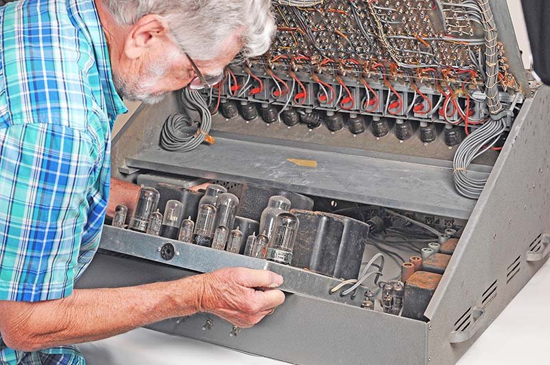
(reference — courtesy Nuts & Volts / David Goodsell)
2.3.2 ES-2 — Amplifier Power Supply
Purpose: To supply regulated high-voltage DC and filament AC to the 15 ES-201 operational amplifier modules.
Power outputs (from the 1956 Heath brochure):
Table 2 — Power outputs (from the 1956 Heath brochure):
| Rail | Voltage | Max current | Purpose |
|---|---|---|---|
| HV+ | +250 V regulated | 250 mA | Plate supply (B+) for op-amps |
| HV− | −250 V regulated | 250 mA | Negative plate supply |
| Grid-bias | −450 V regulated | 50 mA | Grid-bias supply for output stage |
| Filament winding 1 | 6.3 VAC | 12 A | ES-201 tube heaters (main winding) |
| Filament winding 2 | 6.3 VAC | 2.5 A | ES-201 tube heaters (auxiliary winding) |
Danger — The ES-2 generates −450 V DC on the bias rail and ±250 V on the HV rails. These voltages are lethal. The supply filter capacitors store substantial energy even with mains power removed. Allow a minimum of five minutes after switch-off and verify rail voltages with an isolated meter before touching any internal conductor. The −450 V rail in particular has a relatively modest current rating (50 mA) but the stored charge in the filter capacitors is sufficient to cause cardiac arrest.
Internal construction: The ES-2 is built on a substantial aluminium chassis approximately 43 lb (19.5 kg). It contains the following discrete passive elements, all of which are candidates for replacement during restoration (see Vol 4):
- 16 large axial electrolytic capacitors, values ranging from approximately 20 µF @ 350 V to 70 µF @ 350 V
- Multiple power-type carbon-composition resistors (bleeder/dropping)
- Multiple smaller electrolytic capacitors in the regulator stages
- Paper/wax capacitors in filter sections
The ES-2 tube complement (13 tubes per the 1956 Heath brochure): 1× 5651, 3× 12AX7, 3× 6U8, 2× 6080, 1× 6BX7, 2× 5R4GY, 1× 5U4GB. The 5651 provides the voltage reference; the 12AX7 and 6U8 tubes form the error-amplifier and regulator stages; the 6080 and 6BX7 are series-pass regulators; the 5R4GY and 5U4GB are rectifiers. This is consistent with a classic vacuum-tube shunt/series regulator topology typical of 1950s high-voltage regulated supplies.
Regulator architecture: The ES-2 employs a classic vacuum-tube shunt/series regulator arrangement. A reference voltage (typically a gas-discharge voltage-regulator tube, VR type) is compared against a fraction of the output; the error is amplified and applied to a series-pass regulator tube to hold the output constant against load and line variations. The ±250 V outputs must be stable to within the amplifier-balance budget; the Operational Manual calibration procedure (p. 9–10) calls for the operator to verify outputs with the coefficient potentiometer-set jacks connected to the meter.
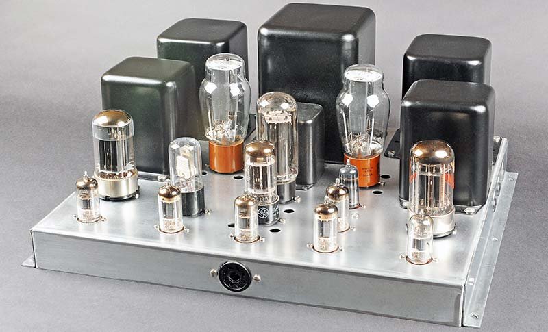
(reference — courtesy Nuts & Volts / David Goodsell)
2.3.3 ES-50 — Reference Power Supply
Purpose: To supply accurate, stable ±100 V DC reference voltages from which the operator derives scaled coefficient voltages for patching.
Power outputs:
Table 3 — Power outputs:
| Rail | Voltage | Notes |
|---|---|---|
| REF+ | +100 V regulated | Used as positive coefficient reference |
| REF− | −100 V regulated | Used as negative coefficient reference |
The 1956 brochure states: “Voltage may be varied from zero to plus 100 volts and zero to minus 100 volts.” The ES-50 delivers regulated ±100 V as the reference rail used by all coefficient potentiometers.
Tube complement (per 1956 Heath brochure): 2× 6X4, 2× 6U8, 1× 5651. The 5651 provides the voltage reference; the 6U8 tubes form the error-amplifier and regulator stages; the 6X4 tubes are rectifiers.
Usage: The operator connects a patch cord from the REF+ or REF− jack on the front panel to the wiper of a coefficient potentiometer. The potentiometer divides the reference voltage to any value between 0 V and ±100 V, providing the scaled coefficient required by the problem setup (see Vol 3).
2.3.4 ES-100 — Initial Condition Power Supplies (×3 units)
Purpose: To supply floating (isolated from chassis) DC voltages that set the initial state of integrators at the beginning of a computation run.
Power outputs (per unit):
Table 4 — Power outputs (per unit):
| Per unit | Voltage | Isolation |
|---|---|---|
| Output A | 0–+100 V adjustable | Floating — neither terminal grounded |
| Output B | 0–+100 V adjustable | Floating — neither terminal grounded |
Each ES-100 provides two independent floating 100 V supplies, giving a system total of six floating IC supplies across the three modules. The floating characteristic is essential: the initial-condition voltage must be applied as a differential across the integrator capacitor without creating a ground loop that would disturb the signal reference.
Tube complement (per 1956 Heath brochure): 2× OB2 per unit. The OB2 is a gas-discharge voltage-regulator tube that stabilises the floating IC supply output.
Operation: When the operator places the system in INITIAL CONDITION (IC) mode via the front-panel relay switches, the IC supply voltages are switched onto the integrating capacitors through the operate/hold relay contacts. When the relay switches to OPERATE, the IC supply is disconnected and the capacitor retains the charged initial condition until the computation runs.
2.3.5 ES-151 — Relay Power Supply
Purpose: To supply the DC power required to operate the two operational relays on the front panel. These relays switch each integrator between its OPERATE and INITIAL CONDITION states.
Power outputs (per 1957 brochure):
Table 5 — Power outputs (per 1957 brochure):
| Rail | Voltage |
|---|---|
| Relay coil A | 50 V DC |
| Relay coil B | 50 V DC |
Tube complement: None. The ES-151 is a passive ~50 V relay supply network; it contains no vacuum tubes. The relay coil voltages are non-critical and do not require active regulation.
Usage: The relays are DPDT (double-pole double-throw) electromechanical devices. In the IC state the relay connects the integrator input to the initial-condition voltage source. In the OPERATE state the relay connects the integrator input to the summing junction from the patch cords. A third relay state, HOLD (sometimes called POTSET), opens both connections so that the integrator capacitor holds its last computed value without change — used to freeze a computation for meter readout.
2.3.6 ES-201 — DC Operational Amplifier (×15 units)
The ES-201 is the primary computing element. The ES-400 contains fifteen identical modules, each a self-contained high-gain DC amplifier on a phenolic printed-circuit board housed in a sheet-metal chassis approximately 4 inches wide.
This is the heart of the machine. Every description that follows in Sections 5 and 6 refers to the ES-201.
Published electrical specifications:
Table 6 — Published electrical specifications:
| Parameter | Value | Source |
|---|---|---|
| Open-loop gain | ≈ 50,000 (nominal) | Research guide / brochure |
| Signal input range | ±100 V | Operational Manual |
| Output voltage range | ±100 V | Operational Manual / brochure |
| Output current | 10 mA maximum | Brochure |
| Integration time constant | 1 s (with 1 MΩ input, 1 µF feedback) | Research guide |
| Overload indicator | NE-51 neon lamp | Operational Manual |
Tube complement per module:
Table 7 — Tube complement per module:
| Position | Type | Class | Role |
|---|---|---|---|
| V1 | 12AX7 | Dual triode, high µ | Differential input / first gain stage |
| V2 | 6BQ7 | Dual triode, TV-tuner type | Intermediate gain stage |
| V3 | 6BH6 | Sharp-cutoff pentode | Output / buffer stage |
| — | NE-51 | Neon indicator lamp | Overload / saturation indication |
Full system tube count:
- 15 ES-201 modules × 3 tubes = 45 signal-path tubes visible through the top panel
- Additional tubes in ES-2, ES-50, ES-100 (×3), ES-151, ES-505 power supplies and oscillator
- Total system: 73 vacuum tubes (per the Research Guide; individual supply-side tube types not all enumerated in sources at hand)
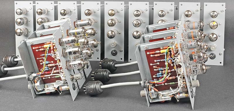
(reference — courtesy Nuts & Volts / David Goodsell)
2.3.7 ES-505 — Repetitive Oscillator
Purpose: To provide automatic repetitive cycling of the computation — alternating between IC (reset) and OPERATE (run) states at an adjustable rate — so that the solution waveform can be displayed continuously on an oscilloscope.
Specifications:
Table 8 — Specifications:
| Parameter | Value |
|---|---|
| Frequency range | 0.6 Hz to 6 Hz |
| Control | Front-panel knob |
| Output | Drives relay coils via ES-151 supply |
Tube complement (per 1956 Heath brochure): 1× 6J6. The 6J6 is a dual triode used as the oscillator element.
Usage: When the REPETITIVE switch on the front panel is placed in the ON position, the ES-505 drives the relay system through its oscillation cycle. The oscilloscope then shows a continuously refreshed trace of the computation. For a 1 Hz rate the computer runs a 0.5 s computation followed by a 0.5 s reset, giving a clearly visible display without flicker. For slow problems a rate of 0.6 Hz may be used; for fast-display work the 6 Hz upper limit is used.
2.3.8 ES-600 — Function Generator (Optional Accessory)
Purpose: To generate arbitrary piecewise-linear functions of a computer variable for use as nonlinear elements in a patch.
Architecture: The ES-600 uses ten straight-line segments — five in the positive direction and five in the negative direction — each defined by a SLOPE potentiometer and a BREAK VOLTAGE setting. The Operational Manual (p. 19–20, Figure 23) shows the front panel: two rows of five pots labeled SLOPE 1–5 and five pots labeled BREAK VOLTAGE 1–5, one set for positive and one for negative.
Connection: The ES-600 connects to the ES-400 cabinet via a 4-pin Varicon socket on the back panel (Operational Manual p. 18, Figure 25). The back panel has three Varicon sockets; the Function Generator uses the one labeled FUNCTION GENERATOR (±V). Power comes from the ES-2 supply rails through this connector.
Input/output: The input voltage (the computer variable to be transformed) is applied to the ES-600 input jack; the output is the piecewise-linear function f(x) available at the output jack for patching elsewhere on the panel.
Electrical requirements (per 1956 Heath brochure): +250 V @ 16 mA, −250 V @ 16 mA, 117 VAC @ 100 mA; drawn from the ES-400 rear-panel Varicon connector. Input/output: F(x) output range ±100 V; accuracy 0.5%; 10 segments (five positive, five negative). Price: $69.95 kit. The ES-600 is an optional accessory, frequently absent from surviving units. Its use is described further in Vol 6.
2.3.9 ES-401 — Constant-Voltage Transformer
Purpose: To regulate the 110 V / 60 Hz mains supply delivered to the sub-assemblies against line-voltage fluctuations.
Rating: 250 VA.
The ES-401 is a ferro-resonant (constant-voltage) transformer. It holds its secondary output within approximately ±1% for primary input variations of ±15%. This isolation is important in a DC analog computer because mains-frequency ripple and voltage fluctuations would otherwise modulate the HV rail and appear as drift or noise at the amplifier outputs. The ES-401 mounts in the bottom bay of the ES-400 cabinet.
2.4 Power Supplies — Rail Architecture
2.4.1 Power tree
       110 V / 60 Hz MAINS
              │
              ▼
       ┌──────────────┐
       │  ES-401 CVT  │ 250 VA ferro-resonant
       │  250 VA      │
       └──────┬───────┘
              │
     ┌────────┴────────┬──────────────┬────────────┐
     ▼                 ▼              ▼            ▼
┌─────────┐      ┌─────────┐   ┌──────────┐  ┌─────────┐
│  ES-2   │      │  ES-50  │   │ ES-100   │  │ ES-151  │
│         │      │         │   │ (×3)     │  │         │
│ +250 V  │      │ +100 V  │   │ 2×float  │  │ 50 V    │
│ −250 V  │      │ −100 V  │   │ 100 V ea │  │ 50 V    │
│ −450 V  │      │ (ref)   │   │ (IC)     │  │ (relay) │
│ 6.3 VAC │      └────┬────┘   └────┬─────┘  └────┬────┘
└────┬────┘           │             │              │
     │                │             │              │
     ▼                ▼             ▼              ▼
ES-201 ×15     Patch field    Integrator IC   Operate/IC
(plate/bias/   coeff. pots    switches        relays
 filament)
Figure 2 — Power distribution tree.
2.4.2 Rail interdependencies
Table 9 — Rail interdependencies
| Rail | Supplied by | Consumers | If rail fails |
|---|---|---|---|
| +250 V | ES-2 | ES-201 plates | All amplifiers dead; outputs clamp |
| −250 V | ES-2 | ES-201 plates (negative side) | All amplifiers dead |
| −450 V | ES-2 | ES-201 grid-bias networks | All amplifiers dead or severely clipped |
| 6.3 VAC (×2) | ES-2 (two windings) | All ES-201 tube heaters | All amplifiers fail after tube cool-down |
| +100 V | ES-50 | Patch reference jacks | No coefficient reference; patch voltages wrong |
| −100 V | ES-50 | Patch reference jacks | No negative coefficient reference |
| 0–100 V (float) | ES-100 ×3 | IC relay contacts → integrator inputs | Integrators cannot be preset |
| 50 V (×2) | ES-151 | Operate/IC relay coils | Cannot switch IC/OPERATE; stuck in one mode |
Danger — The ±250 V and −450 V rails remain live for a substantial period after the HIGH VOLTAGE switch is turned off. The ES-2 filter capacitors are rated 20 µF to 70 µF at 350 V each. The energy stored in a single 70 µF capacitor charged to 350 V is ½CV² ≈ 4.3 J — sufficient to cause serious or fatal injury. Always discharge capacitors through a resistive load and verify with a meter before probing internal nodes. The HIGH VOLTAGE pilot lamp indicates that the HV switch has been placed ON, but it does not indicate that the rails have discharged after switch-off.
2.4.3 Mains power budget
Table 10 — Mains power budget
| Sub-assembly | Approximate contribution | Notes |
|---|---|---|
| ES-2 (15 op-amps) | ~350 W | Dominates; filament current alone is ~90 W |
| ES-50, ES-100 (×3), ES-151 | ~50 W combined | Estimated; not separately stated |
| ES-505 | ~10 W | Small oscillator |
| Front panel lamps/meter | ~5 W | |
| ES-401 CVT (losses) | ~35 W | ~14% typical ferro-resonant loss at rated load |
| Total | ~450 W | Per Research Guide specification |
2.5 The Vacuum-Tube DC Operational Amplifier
2.5.1 Design philosophy
The ES-201 is a three-stage, DC-coupled, inverting voltage amplifier with high open-loop gain. Its design follows the classical analog computer op-amp topology first described by Lovell (Bell Labs, 1946) and subsequently standardized across industry. The key requirements that shaped this topology are:
- DC coupling throughout — integration requires that the amplifier respond faithfully down to 0 Hz; any coupling capacitor would create a lower cutoff frequency and introduce droop in the integrated output.
- High open-loop gain (≥ 10⁴) — high gain drives the closed-loop error to a small fraction of output swing; for an integrator with 1 MΩ / 1 µF, the gain–bandwidth product must support the required integration accuracy.
- Stable quiescent point (low drift) — the input stage must be balanced so that thermal drift of the first tube does not integrate to a large output offset over the computation run time. The 12AX7 dual triode in a differential configuration largely cancels common-mode thermal drift.
- Output capability ±100 V at 10 mA — the output must drive patch resistors in parallel (multiple subsequent amplifier inputs) without sagging.
2.5.2 Stage-by-stage topology
SUMMING JUNCTION
(virtual ground)
      │
      │  Plug-in input resistors R_in (1 MΩ typ.)
      │◄────────────────────────────── Input V1, V2, …
      │
      │ ──────────────────────────────────────────────────────────
      │                   ES-201  SIGNAL PATH
      ▼
┌─────────────────────────────────────────────────────────────────┐
│  STAGE 1  —  12AX7  dual triode  (input / differential)        │
│                                                                 │
│  Triode A: summing junction → grid; plate drives stage 2        │
│  Triode B: balance pot wiper → grid; plate tied to B+          │
│  (differential pair; Triode B cancels thermal drift of A)      │
│                                                                 │
│  Gain contribution: ≈ 60–80× (typical 12AX7 µ ≈ 100,          │
│  loaded by subsequent stage)                                   │
└──────────────────────────┬──────────────────────────────────────┘
                           │
                           ▼
┌─────────────────────────────────────────────────────────────────┐
│  STAGE 2  —  6BQ7  dual triode  (intermediate gain)            │
│                                                                 │
│  Triode A: input from stage 1; plate drives stage 3            │
│  Triode B: phase-splitter or additional gain element            │
│  (6BQ7 is a low-capacitance, high-transconductance TV-tuner    │
│   type; Gm ≈ 5.2 mA/V; µ ≈ 20; chosen for bandwidth)         │
│                                                                 │
│  Gain contribution: ≈ 60–100× depending on plate load          │
└──────────────────────────┬──────────────────────────────────────┘
                           │
                           ▼
┌─────────────────────────────────────────────────────────────────┐
│  STAGE 3  —  6BH6  sharp-cutoff pentode  (output / driver)     │
│                                                                 │
│  Grid biased from −450 V rail via resistor divider             │
│  Screen supplied from +250 V rail                              │
│  Plate: output node; drives feedback network and load          │
│  6BH6 Gm ≈ 4.3 mA/V; ra ≈ 1 MΩ; chosen for voltage swing     │
│                                                                 │
│  Output voltage: ±100 V; output current: 10 mA max             │
└──────────────────────────┬──────────────────────────────────────┘
                           │
                           ▼  OUTPUT jack
                           │
              ┌────────────┴────────────────┐
              │                             │
       Plug-in feedback             NE-51 neon lamp
       element (C_f or R_f)        (across output;
       to summing junction         ignites at ~65 V
                                   when output clips)
Figure 3 — ES-201 three-stage signal path (conceptual; not all bias components shown).
2.5.3 Gain budget
With the three stages in cascade and negative feedback closing through the plug-in feedback impedance:
Table 11 — With the three stages in cascade and negative feedback closing through the plug-in feedback impedance
| Stage | Approximate open-loop gain |
|---|---|
| 12AX7 (stage 1) | 60–80× |
| 6BQ7 (stage 2) | 60–100× |
| 6BH6 (stage 3, pentode) | 100–150× |
| Cascaded open-loop (product) | ~360,000–1,200,000 |
| Nominal specified gain | ≈ 50,000 |
The discrepancy between the theoretical product and the specified 50,000 reflects practical factors: inter-stage loading, the cathode-follower or common-cathode output topology of individual stages, and intentional frequency compensation that reduces gain at higher frequencies to maintain stability with feedback. An effective gain of 50,000 is sufficient to drive the closed-loop error to less than 0.002% of full-scale output for a feedback factor approaching unity (summer with equal R).
2.5.4 Differential input and balance
The 12AX7 is the only commercially available dual triode in a single 9-pin Noval envelope with matched sections, making it the natural choice for the input differential pair. In the ES-201 topology:
- Triode A (signal side) receives the summing-junction voltage on its grid. Because the summing junction is a virtual ground (held near 0 V by the high open-loop gain and feedback), the grid voltage is small but the triode amplifies it to a large plate voltage swing.
- Triode B (balance side) has its grid connected to the BALANCE potentiometer wiper on the front panel. Adjusting this pot trims the quiescent operating point so that the output is 0 V when the input is 0 V (summing junction shorted to ground).
The Operational Manual (p. 11) prescribes the balance procedure:
- Short the summing junction to ground (remove all plug-in input resistors).
- Select the amplifier on the AMPLIFIER OUTPUT switch.
- Connect the AMPLIFIER OUTPUT jack to the METER jack.
- Adjust the BALANCE pot (labeled on the front panel for each of the 15 amplifiers) until the front-panel DC milliammeter reads zero.
- Remove the short from the summing junction and reinstall plug-in components.
Unbalanced amplifiers integrate the offset voltage, causing the output to drift toward the rail over time even with no signal applied. For long computation runs (several seconds), re-balancing before each run is recommended.
2.5.5 Drift and limiting factors
Table 12 — Drift and limiting factors
| Drift source | Mechanism | Mitigation |
|---|---|---|
| 12AX7 grid current | Leakage through glass envelope, especially warm | Use selected low-leakage sections; keep tube cool |
| 12AX7 heater-cathode leakage | Capacitive and resistive coupling of 6.3 V AC to cathode | 6.3 V AC filament supply must be floated at cathode potential; balanced winding helps |
| Plate supply ripple | ±250 V supply must have negligible 120 Hz ripple | ES-2 regulation and LC/RC filtering |
| Ambient temperature | Triode parameters shift with temperature | Warm-up time of 30 min recommended before precision work |
| Feedback component tolerance | Resistors in 1 MΩ summing network must be accurate | Original manual specifies 1% tolerance; Goodsell used 1% metal film on restoration |
2.5.6 Overload detection — NE-51 neon lamp
The NE-51 (or equivalent NE-2) neon indicator lamp is connected between the output node and a current-limiting resistor to a supply rail. The neon striking voltage is approximately 65–70 V; when the amplifier output approaches ±100 V (saturation), the neon fires and glows orange, alerting the operator that the amplifier is railed. Because an overloaded integrator loses its computed value (the capacitor charges to the rail), the NE-51 indication is an important real-time diagnostic. All 15 indicators are visible simultaneously from the front of the machine.
2.6 Schematic Walk-Through by Stage
This section traces the signal from the patch field through the ES-201 to the output, following the topology described in Section 5. Component values are those stated in sources or derived from standard 12AX7/6BQ7/6BH6 application data; exact resistor and capacitor values at each node are documented in the ES-201 Service Manual (available separately from Elektrotanya/Schematics Unlimited — see Vol 4).
2.6.1 Plug-in passive elements (front panel)
INPUT JACKS (banana)
    │
    ├─── 1 MΩ plug-in resistor ──► SUMMING JUNCTION (e)
    │
    ├─── 100 kΩ plug-in resistor ──► SUMMING JUNCTION (e)
    │
    └─── (additional inputs, up to panel limit)

FEEDBACK JACK (banana)
    │
    ├─── 1 MΩ resistor ──► SUMMING JUNCTION (e)   [summer configuration]
    │         OR
    └─── 1 µF capacitor ──► SUMMING JUNCTION (e)  [integrator configuration]
The ratio of feedback impedance Z_f to input impedance Z_in determines the closed-loop gain (summer) or integration time constant (integrator):
- Summer (resistors only): A_CL = −Z_f / Z_in = −R_f / R_in. With 1 MΩ feedback and 1 MΩ input, gain = −1 (inverter). With 100 kΩ input and 1 MΩ feedback, gain = −10.
- Integrator (capacitor feedback): Output = −(1 / R_in C_f) ∫ V_in dt. With 1 MΩ / 1 µF, τ = 1 s exactly.
2.6.2 Stage 1 — 12AX7 differential input
The 12AX7 is a high-µ (amplification factor µ ≈ 100) dual triode. In the ES-201:
Table 13 — The 12AX7 is a high-µ (amplification factor µ ≈ 100) dual triode. In the ES-201
| Node | Detail |
|---|---|
| V1A grid (pin 2) | Driven by summing junction e through grid resistor |
| V1A cathode (pin 3) | Common cathode resistor to −250 V (or local negative rail) |
| V1A plate (pin 1) | Drives V2 (6BQ7) grid through DC coupling network |
| V1B grid (pin 7) | BALANCE potentiometer wiper |
| V1B cathode (pin 8) | Common to V1A cathode (differential pair) |
| V1B plate (pin 6) | Tied to B+ or to a load resistor as a current source |
Because both cathodes share a common resistor (tail resistor), the pair is a long-tailed differential pair. An increase in V1A plate current is mirrored as a decrease in V1B plate current. Common-mode signals (equal voltages applied to both grids simultaneously, such as slow thermal drift of the tube parameters) produce little differential output — the balance point shifts only slightly. Differential signals (summing junction deviating from zero while balance grid is held fixed) produce full gain.
2.6.3 Stage 2 — 6BQ7 intermediate gain
The 6BQ7A is a dual triode designed for TV tuner applications, featuring low interelectrode capacitance and matched sections. In the ES-201 it provides additional voltage gain between the 12AX7 output and the output pentode.
Table 14 — Stage 2 — 6BQ7 intermediate gain
| Node | Detail |
|---|---|
| V2A grid | DC-coupled from V1A plate; no coupling capacitor |
| V2A plate | Drives V3 (6BH6) control grid through DC coupling |
| V2B | Used as second amplifying element or phase-splitter depending on exact topology (service schematic required to confirm) |
| Heater | 6.3 V AC (shared bus with all other ES-201 heaters) |
Typical 6BQ7A parameters: µ ≈ 17–22, Gm ≈ 5.2 mA/V, ra ≈ 4 kΩ. The choice of the 6BQ7 over more common triodes reflects Heath’s preference for a low-plate-resistance tube to drive the pentode grid without signal loss.
2.6.4 Stage 3 — 6BH6 output pentode
The 6BH6 is a sharp-cutoff (remote-cutoff) pentode originally designed for IF amplifiers in television and FM receivers. Its characteristics:
Table 15 — The 6BH6 is a sharp-cutoff (remote-cutoff) pentode originally designed for IF amplifiers in television and FM receivers. Its characteristics
| Parameter | Typical value |
|---|---|
| Transconductance Gm | 4.3 mA/V |
| Plate resistance ra | ~1 MΩ |
| Screen voltage | From +250 V rail through dropping resistor |
| Grid-bias supply | −450 V rail via resistor network to control grid |
| Max plate dissipation | 2.75 W |
| Max plate voltage | 330 V |
In the ES-201, the 6BH6 operates in a configuration that allows the plate voltage to swing from near 0 V to approximately +250 V relative to the negative rail, providing the full ±100 V output range referenced to the machine’s signal ground (the midpoint between +250 V and −250 V rails).
The −450 V bias supply is used to provide a negative grid bias for the 6BH6 that is more negative than the most negative signal that the preceding stages can deliver to the grid. This ensures the pentode does not be driven into grid current even at maximum output swing.
2.6.5 NE-51 overload limiter
     OUTPUT (±100 V max)
          │
          ├──────────────────► Output jack (to patch field)
          │
          └──► [R_limit, ~100 kΩ] ──► NE-51 anode
                                        NE-51 cathode ──► fixed bias or supply

                   NE-51 strikes at ≈ 65–70 V between its terminals.
                   When output approaches ±100 V, the voltage across
                   R_limit + NE-51 exceeds striking voltage; lamp glows.
The NE-51 does not hard-clamp the output (it is not a diode in the feedback path). It is a visual indicator only. The actual overload is set by the amplifier’s plate supply rail (+250 V / −250 V), which is the hard limit.
2.6.6 Front panel — the patch field
             AMPLIFIER MODULES  (ES-201 ×15)
             ┌──────────────────────────────────────────────┐
             │ AMP 1         AMP 2         ...  AMP 15      │
             │ ○INPUT 1A    ○INPUT 2A           ○INPUT 15A  │ ← 1 MΩ banana jacks
             │ ○INPUT 1B    ○INPUT 2B           ○INPUT 15B  │ ← 100 kΩ banana jacks
             │ ○FB 1        ○FB 2               ○FB 15      │ ← feedback jacks
             │ ●OUTPUT 1    ●OUTPUT 2           ●OUTPUT 15  │ ← output jacks
             └──────────────────────────────────────────────┘
                                  │
             ┌────────────────────┴───────────────────────┐
             │          COEFFICIENT POTENTIOMETERS         │
             │  POT 1  POT 2  ...  POT 30  (30× standard) │
             │  AUX POT A  AUX POT B  (2× 10-turn)        │
             └────────────────────┬───────────────────────┘
                                  │
             ┌────────────────────┴───────────────────────┐
             │            REFERENCE RAILS                  │
             │   +100 V (ES-50)        −100 V (ES-50)     │
             │   +10 V tap             −10 V tap           │
             └────────────────────────────────────────────┘
Figure 4 — Patch field signal-flow topology.
The operator’s patch cords (2 mm banana plug, various lengths) make all signal connections. The Operational Manual (p. 12–13) states that polystyrene or Teflon-dielectric capacitors should be preferred for integration feedback because their leakage is negligible; other types introduce leakage current that appears as an integrator bias.
2.6.7 Patch cord color convention (per Operational Manual, p. 12)
Table 16 — Patch cord color convention (per Operational Manual, p. 12)
| Color | Conventional use |
|---|---|
| Black | Signal ground / 0 V reference |
| Red | Positive signal path |
| Yellow | Signal cable between amplifiers |
| Green | Signal cable between amplifiers (second signal) |
| Other | Coefficient connections, IC supply connections |
The Operational Manual does not mandate a strict color code but recommends consistency within a patch to aid troubleshooting.
2.7 Front Panel — Controls and Indicators
(reference — courtesy Nuts & Volts / David Goodsell)
2.7.1 Control inventory
Table 17 — Control inventory
| Item | Quantity | Purpose |
|---|---|---|
| Banana-plug signal jacks | 364 | All patch connections |
| Coefficient potentiometers (10-turn, standard) | 30 | Scale coefficients 0–1 (×10 with 10:1 pad) |
| Auxiliary potentiometers (10-turn) | 2 | Higher-precision coefficients |
| Toggle switches | 52 | Mode selection (OPERATE / IC / HOLD), REPETITIVE, HIGH VOLTAGE, POWER, relay controls |
| Back-panel Varicon connectors | 14 | External equipment (oscilloscope X/Y, function generator, accessory supplies) |
| DC milliammeter | 1 | Reads selected amplifier output or pot setting in DC volts |
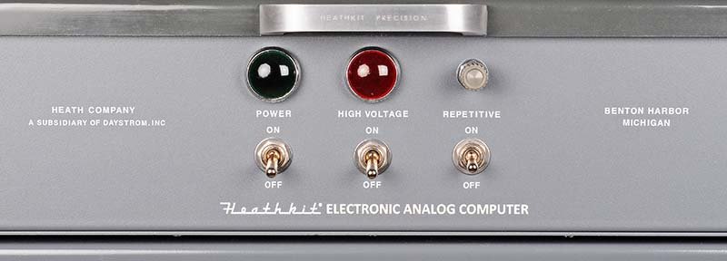
| Pilot lamps | 2 | POWER ON (green), HIGH VOLTAGE ON (red) |
| Front-panel meter jacks (banana) | 2 | External meter connection |
| NE-51 overload lamps | 15 | One per amplifier, visible from front |
(reference — courtesy Nuts & Volts / David Goodsell)
Danger — The HIGH VOLTAGE ON pilot lamp (red) indicates the ±250 V / −450 V rails are energised. The POWER ON lamp (green) indicates only that mains is applied to the filament transformer. It is possible for the filaments to be live (tubes glowing) while HV is off. Conversely, the HV lamp extinguishes immediately when the switch opens, but the rails remain above 50 V for many seconds due to capacitor discharge time. Do not treat lamp extinction as proof of safe voltage.
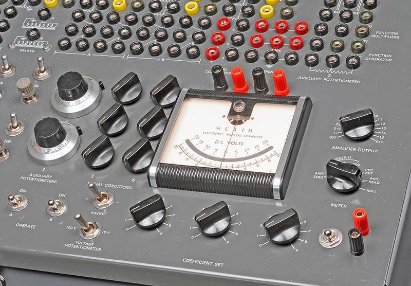
2.7.2 Front panel — the DC milliammeter
The front-panel meter is a DC milliammeter movement with a scale reading DC Volts (calibrated in V at a specific shunt/multiplier ratio). The Operational Manual (p. 9) calls it out as a meter used to measure:
- AMP ZERO — connect AMPLIFIER OUTPUT jack to METER jack; select amplifier 1–15 with the AMPLIFIER OUTPUT rotary switch; use for balancing (zeroing) the amplifier output.
- POT SET — the meter reads the potentiometer wiper voltage, allowing precise coefficient setting without needing an external voltmeter.
- POT READ — reads the pot output with reference connected; verifies coefficient value.
- NULL — used with the AMPLIFIER OUTPUT jack for zero-checking (output nulling).
The meter range is stated as DC Volts on the face of the original (readable in the Goodsell photograph figure 7); the exact full-scale deflection is not specified in the Operational Manual text as seen in the rendered pages. The Research Guide states the output range is ±100 V.
2.8 Sub-Assembly Specifications Summary Table
Table 18 — Sub-Assembly Specifications Summary Table
| Sub-assembly | Qty | Tube types | Key outputs | Primary load |
|---|---|---|---|---|
| ES-2 | 1 | 1×5651, 3×12AX7, 3×6U8, 2×6080, 1×6BX7, 2×5R4GY, 1×5U4GB (13 total) | +250 V / −250 V / −450 V @ stated currents; 6.3 VAC 12 A + 6.3 VAC 2.5 A | 15× ES-201 |
| ES-50 | 1 | 2×6X4, 2×6U8, 1×5651 | ±100 V reference | Patch coefficient pots |
| ES-100 | 3 | 2×OB2 per unit | 2× floating 0–100 V (per unit) | IC relay contacts |
| ES-151 | 1 | None (passive relay network) | 2× ~50 V | Operate/IC relay coils |
| ES-201 | 15 | 12AX7, 6BQ7, 6BH6, NE-51 | ±100 V @ 10 mA; gain ≈ 50,000 | Patch field loads |
| ES-505 | 1 | 1×6J6 | 0.6–6 Hz square/relay drive | Operate/IC relay coils |
| ES-600 | 0 or 1 | Not specified in available sources | f(x) piecewise-linear output | Patch field |
| ES-401 CVT | 1 | None (magnetic) | Regulated 110 VAC | All sub-assemblies |
Note — Tube complements for ES-2, ES-50, ES-100, ES-151, and ES-505 are from the 1956 Heath brochure (CHM accession 102646297). The ES-600 tube types are not specified in any available source at hand.
2.9 ES-400 vs. EC-1 Hardware Comparison
The Heathkit EC-1 is the smaller desktop companion to the ES-400. Both machines use the ES-201 operational amplifier module.
Table 19 — ES-400 vs. EC-1 Hardware Comparison
| Parameter | ES-400 (H-1) | EC-1 |
|---|---|---|
| Op-amp design | 15× ES-201 (12AX7 + 6BQ7 + 6BH6) | Nine single 6U8 amplifiers |
| Total vacuum tubes (all) | 73 | ~17 active tubes |
| Output voltage range | ±100 V | ±60 V |
| Amplifier gain | ≈ 50,000 | Different design (6U8) |
| Banana-plug jacks (patch) | 364 | ~120 (estimated) |
| Coefficient pots | 30 + 2 aux (10-turn) | 5 coefficient pots |
| Repetitive oscillator | ES-505 (built-in) | Built-in |
| Function generator option | ES-600 (optional) | Not available |
| Cabinet format | Floor-standing console | Desktop |
| Weight | 168 lb | Much lighter |
| Original price | $945 (Group C, 1956) | $199.95 (kit, 1959) |
| Production period | 1956–1962 | 1959–1963 |
The EC-1 Operational Manual is directly applicable to ES-400 programming because the computing elements are identical. Restoration procedures for ES-201 modules developed on an EC-1 apply directly to the ES-400.
2.10 Plug-in Component Kits
The Operational Manual (p. 12, Figure 14) shows the plug-in resistors and capacitors used to configure each ES-201 as a summer, integrator, or inverter. These are not permanently installed on the amplifier PCB — they are inserted into the banana-plug jacks on the front panel at setup time.
2.10.1 Standard plug-in values (per Operational Manual)
Table 20 — Standard plug-in values (per Operational Manual)
| Component | Value | Configuration |
|---|---|---|
| Input resistor | 1 MΩ | Standard input; gain = 1 with 1 MΩ feedback |
| Input resistor | 100 kΩ | Gain = 10 with 1 MΩ feedback |
| Feedback resistor | 1 MΩ | Summer/inverter |
| Integrating capacitor | 1 µF | Integrator, τ = 1 s with 1 MΩ input |
| Integrating capacitor | 0.1 µF | Integrator, τ = 0.1 s (speed-up) |
The Operational Manual states: “The capacitors are large and heavy to mount on the front of the panel. The best satisfactory ones are polystyrene.” This is a critical material specification: polystyrene capacitors have the lowest dielectric absorption of any practical capacitor type available in the 1950s (and remain among the best today), minimising integrator memory effects where the capacitor partially “remembers” a previous charge and corrupts the next computation run. Modern equivalent for restoration: polystyrene (now rare) or C0G / NP0 ceramic.
Note — The original Heath plug-in resistors and capacitors for the ES-400 are themselves collector items. In their absence, standard radial-lead components with bare banana-pin leads soldered on will function correctly provided the dielectric type is appropriate (polystyrene or C0G/NP0 for integrating capacitors; metal film for input and feedback resistors).
2.11 Diode Function Generation
The front panel includes four dual bias diodes (per the Research Guide) used for nonlinear function generation without the ES-600 accessory. The Operational Manual (p. 17, Figure 21) shows two sections:
- Positive diodes: bias voltage set by a pot; the diode conducts and clips the signal when the input exceeds the bias level.
- Negative diodes: same in the negative direction.
By connecting these diodes in the patch field with appropriate summer amplifiers, the operator can implement:
- Dead zones (no response below a threshold)
- Limiters (hard clipping at a set voltage)
- Piecewise-linear approximations to nonlinear functions (combined with coefficient pots)
The Operational Manual gives a worked example of two-diode function generation with Figures 21–22.
2.12 Known Failure Points → See Vol 4
The following components are documented failure points identified through the Goodsell restoration and general vacuum-tube analog computer maintenance practice. Detailed replacement procedures, part numbers, and re-capping sequences are in Vol 4 — Restoration & Maintenance.
Table 21 — Known Failure Points → See Vol 4
| Item | Failure mode | Urgency |
|---|---|---|
| ES-2 electrolytic filter caps (16 units, 20–70 µF, 350 V) | Dry out → excess ripple on HV rails → op-amp drift | Replace all; do not reform |
| ES-201 PCB electrolytic caps | Dry out → drift, oscillation | Replace all |
| ES-201 paper/wax capacitors | Leakage → integrator offset | Replace all |
| ES-201 carbon-composition resistors | Drift (±10–20% typical after 60 years) | Replace with 1% metal film |
| ES-201 tube sockets | Contact oxidation → intermittent tube contact | Replace with new |
| 12AX7 tubes | Grid current increase with age | Test; select low-leakage |
| 6BQ7 tubes | Vintage NOS supply shrinking | Source and test before restoration |
| 6BH6 tubes | Generally available; some drift in cut-off | Test; replace weak units |
| NE-51 neon lamps | Eventual failure to strike; one failed in Goodsell restoration | Replace all as a set |
| Front panel banana jacks (364 units) | Contact oxidation; stripped threads | Clean with DeoxIT; replace damaged units |
| ES-401 CVT | Very reliable; inspect for winding insulation | Clean; verify output |
| ES-2 transformer cores | Rust on exposed cores | Disassemble, prime, satin-black paint |
| Interior chassis panels | Rust | Sandblast; powder-coat textured grey |
(reference — courtesy Nuts & Volts / David Goodsell)
2.13 Restoring the Balance Network — a Quick-Reference Procedure
Because the balance procedure must be performed before any computation and is fundamental to hardware verification, it is summarised here (full detail in Vol 4):
For each amplifier 1 through 15:

1. Remove ALL plug-in resistors and capacitors from AMP n input/feedback jacks.
2. Short the summing junction to ground (patch cord: INPUT jack → GND jack).
3. Set AMPLIFIER OUTPUT rotary switch → position n.
4. Connect AMPLIFIER OUTPUT jack → METER jack (patch cord).
5. Set METER mode switch → AMP (not POT SET).
6. Adjust BALANCE pot n until front-panel meter reads zero (±0 on scale).
7. Remove the summing-junction short.
8. Repeat for all 15 amplifiers.

After all amplifiers are balanced:
   — Install plug-in components for the intended patch.
   — Switch to INITIAL CONDITION; verify IC voltages.
   — Switch to OPERATE; observe computation.
The Operational Manual states that balance should be checked after the machine has warmed up for at least 30 minutes with all tubes conducting.
2.14 Signal Scaling and the ±100 V Constraint
Every voltage in the ES-400 represents a physical variable scaled so that it fits within the ±100 V output range of the ES-201 amplifiers. This is the central constraint on problem setup and directly reflects the hardware architecture.
SCALING EXAMPLE  —  position of a falling body

  Physical variable:  y  [metres],  range 0 – 100 m
  Machine variable:   e_y [volts],  range 0 – 100 V
  Scale factor:       1 V/m

  Physical variable:  ẏ  [m/s],    range 0 – 44 m/s
  Machine variable:   e_ẏ [volts],  range 0 – 44 V
  Scale factor:       1 V/(m/s)

  Physical variable:  ÿ  = −g = −9.81 m/s²
  Machine variable:   e_ÿ = −9.81 V (constant; from coefficient pot)
  Scale factor:       1 V/(m/s²)

  No rescaling needed: all variables remain within ±100 V.
If the natural scale would overflow (e.g., a variable ranging to ±1000 V in unscaled form), an amplitude scale factor is introduced: 10 V per 100 physical units, so the machine variable stays within ±100 V. Simultaneously, time may be scaled (compressed) by choosing integration time constants shorter than the physical time scale, allowing a slow physical process to run in fast machine time for convenient oscilloscope display. Scaling theory is treated in detail in Vol 3.
Sources
-
Heath Company. Heath Electronic Analog Computer Operational Manual. Benton Harbor, Michigan. (Scanned copy in project folder; rendered pages read for this volume.)
-
Heath Company. Heath Electronic Analog Computer Kit (sales brochure, 1956). Computer History Museum, accession 102646297. (Scanned copy at
heath.analog.1956.102646297.pdfin project folder; all four pages rendered and read for this volume.) -
Goodsell, David. “Restoring the Heathkit ES-400 Computer.” Nuts & Volts Magazine, 2019. (Photographs nv-0319-goodsell-figure02 through figure16 used under reference/educational fair-use caption; courtesy Nuts & Volts / David Goodsell.)
-
AnalogComputers project — ES-400 research compilation (2026).
Comments (0)