Heathkit EC-1 · Volume 8
Heathkit EC-1 — Volume 8 — Cheatsheet (field-grade)
Quick-reference card set distilling Vols 1–7: tube map, jack/pot map, scaling formulas, patch symbols, power-up sequence, recap checklist, triage tree, and high-voltage safety card
Complete Tube Complement
Table 1 — 1.1 Complete Tube Complement
| Ref | Type | Qty | Function | Socket | Failure Mode |
|---|---|---|---|---|---|
| V1–V9 | 6U8A | 9 | DC operational amplifier (pentode + triode per tube) | 9-pin noval | Amp drifts, won’t null; output stuck |
| V10 | 12BH7A | 1 | Repetitive oscillator (multivibrator) | 9-pin noval | REP mode dead; relay won’t cycle |
| V11 | 6AQ5 | 1 | Relay driver / power stage | 7-pin miniature | Relay stays open or stuck closed |
| V12 | 6BH6 | 1 | Auxiliary circuit (control section) | 7-pin miniature | Control circuit malfunction |
| V13 | 0A2 | 1 | VR tube, −150 V rail regulation | 7-pin miniature | −150 V unregulated; blue glow absent |
| V14 | 0B2 | 1 | VR tube, IC supply regulation (100 V section) | 7-pin miniature | IC supply voltages wander |
Note — The 0A2 and 0B2 are cold-cathode voltage-regulator tubes; the purple-blue glow is normal. Absence of glow during operation indicates tube failure or supply fault. See Vol 2 (Hardware & Theory of Operation) for detailed analysis.
6U8A Noval Pinout (per amplifier, V1–V9)
        6U8A  (top view, pins 1–9 clockwise from key)

              ┌─────┐
         1 ──┤     ├── 9
         2 ──┤ 6U8A├── 8
         3 ──┤     ├── 7
         4 ──┤     ├── 6
              └──┬──┘
                 5

  Pin  Section    Function
  ─────────────────────────────────────────
   1   Triode      Grid (cathode follower output stage grid)
   2   Triode      Anode (plate)
   3   Common      Cathode (triode)
   4   Heater      6.3 VAC (one side)
   5   Heater      6.3 VAC (other side / CT)
   6   Pentode     Anode (plate) — high gain stage
   7   Pentode     Screen grid (G2) — starved for high μ
   8   Pentode     Suppressor (G3) — tied to cathode internally
   9   Pentode     Control grid (G1) — signal input
   —   Pentode     Cathode (connected externally to balance circuit)
Tip — The EC-1 operates the pentode screen at low voltage (starved-screen technique) to achieve plate-load gain ≈ 700; positive feedback via the 2.2 MΩ resistor raises total open-loop gain to ≈ 1,000. See Vol 2 (Hardware & Theory of Operation) for derivation.
0A2 / 0B2 Pinout (7-pin miniature, VR tubes)
  Pin   0A2 / 0B2 function
  ──────────────────────────
   1    Anode (+, high side)
   2    NC
   3    NC
   4    Cathode (−, low side)
   5    NC
   6    NC
   7    NC
   Shield: connect to chassis
Regulation voltage: 0A2 = 150 V; 0B2 = 108 V. Operating current range: 5–30 mA for stable regulation. Below 5 mA the discharge extinguishes.
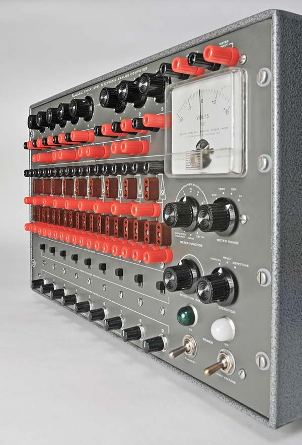
8.1 EC-1 Field Cheatsheet — Panel 2: Front-Panel Jack and Pot Quick-Reference
8.1.1 Front-Panel Overview
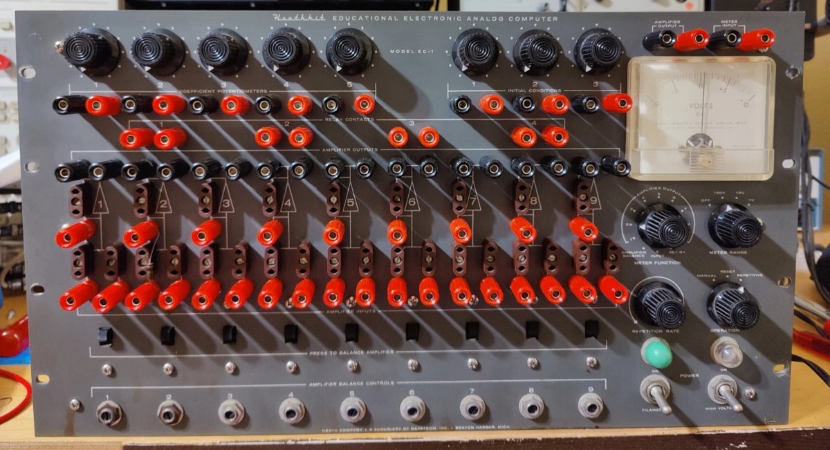
8.1.2 Amplifier Section (×9, numbered 1–9)
Each amplifier block exposes the following jacks and hardware:
Table 2 — Each amplifier block exposes the following jacks and hardware
| Item | Color / Mark | Description |
|---|---|---|
| INPUT jack A | Red banana | One of two inverting summing inputs |
| INPUT jack B | Red banana | Second inverting summing input |
| OUTPUT jack A | Red banana | Signal output (one of two) |
| OUTPUT jack B | Red banana | Second output (paralleled with A) |
| FEEDBACK socket | Brown 2-pin | Plug-in feedback element (R or C) |
| INPUT socket(s) | Brown 2-pin | Plug-in input element(s) (R or C) |
| BALANCE slide switch | Panel toggle | Disconnects amp from problem board; enables null with 1 MΩ / 1 MΩ loop |
| BALANCE trim pot | 3 kΩ WW | Zero-output trim; screwdriver slot |
Note — The two-pin brown sockets (27 total on the chassis) accept plug-in resistor or capacitor modules. Standard values shipped with the kit: 0.1 MΩ, 1 MΩ input resistors; 1 µF Mylar feedback capacitors; 1 MΩ feedback resistors. Additional values are field-fabricated; see Vol 4 (Acquisition & Restoration) for fabrication details.
8.1.3 Meter and Read-Out Section
Table 3 — 2.3 Meter and Read-Out Section
| Control / Jack | Function | Range / Notes |
|---|---|---|
| METER FUNCTION switch | Selects what the meter reads | Positions: SET B+, INPUT, AMPLIFIER BALANCE, AMP 1–9 |
| METER RANGE switch | Full-scale range selector | 1 V / 10 V / 100 V / OFF |
| METER movement | 50-0-50 µA D’Arsonval | Center-zero; reads 1-0-1, 10-0-10, 100-0-100 VDC |
| METER INPUT (red) | External signal input to meter | Active only when FUNCTION = INPUT; 10 kΩ/V sensitivity |
| METER INPUT (black) | Ground reference for above | — |
| AMPLIFIER OUTPUT (red) | Buffered output to scope / recorder | Active when FUNCTION = AMP 1–9 |
| AMPLIFIER OUTPUT (black) | Ground for above | — |
8.1.4 Power and Control Section
Table 4 — 2.4 Power and Control Section
| Control | Function | Notes |
|---|---|---|
| FILAMENT switch | 6.3 VAC heater power | Green pilot lamp |
| HIGH VOLTAGE switch | +300 V / −150 V B+ enable | Clear pilot lamp; interlocked — requires FILAMENT ON |
| OPERATION switch | RESET / MANUAL / REPETITIVE | RESET closes relay contacts (IC loaded, caps discharged) |
| REPETITION RATE knob | Oscillator frequency | 0.1 to 15 cps; clockwise = faster |
| VC trim (chassis rear) | +300 V output adjustment | Set with FUNCTION = SET B+; adjust to meter red mark |
8.1.5 Initial Condition (IC) Supplies (×3)
Table 5 — 2.5 Initial Condition (IC) Supplies (×3)
| Item | Spec | Notes |
|---|---|---|
| Output voltage range | 0–100 VDC (approx. 0–105 V max) | Full CCW = 0 V; CW = max |
| Output current | 5 mA max | Regulated by 0B2 VR tube |
| Grounding | Floating (not ground-referenced) | Must ground one terminal before use; red = + terminal convention |
| Regulation | 0B2 VR tube | Provides ~108 V reference; divider sets output |
8.1.6 Coefficient Potentiometers (×5)
Table 6 — 2.6 Coefficient Potentiometers (×5)
| Item | Value | Terminals on Panel |
|---|---|---|
| COEFF POT 1–5 | 100 kΩ each | One end grounded; wiper (black post) = output; other end (red post) = input |
| Useful range | 0.00–1.00 | Full CCW wiper = 0 V (ground); CW = full input voltage |
Tip — To set a coefficient α, apply the source voltage to the red terminal, take the wiper (black) as the scaled output. The coefficient equals wiper-to-ground / end-to-ground ratio. For α = 0.37: set wiper 37% of rotation from CCW stop.
8.1.7 Relay Contacts (×4 sets, DPST equivalent per set)
Table 7 — 2.7 Relay Contacts (×4 sets, DPST equivalent per set)
| Contact Set | Panel Posts | Typical Use |
|---|---|---|
| RELAY 1A / 1B | Two red + two black | Discharge feedback capacitor on Amp 1 during RESET |
| RELAY 2A / 2B | Two red + two black | Discharge feedback capacitor on Amp 2 during RESET |
| RELAY 3A / 3B | Two red + two black | Available for problem use or additional cap reset |
| RELAY 4A / 4B | Two red + two black | Available for problem use |
Contacts are normally closed (NC) in RESET; open in MANUAL / REPETITIVE. Wire relay contacts in parallel with each integrator’s feedback capacitor to discharge between runs.
8.2 EC-1 Field Cheatsheet — Panel 3: Scaling Formula Card
8.2.1 Amplitude Scaling
The EC-1 output is limited to ±60 V per amplifier (±100 V absolute maximum before clipping). Every problem variable must be mapped into this range.
Amplitude scale factor (a):
      machine variable [V]          x_machine
a  =  ─────────────────────   →   ──────────  = a · x_problem
      problem variable [units]     x_problem
Procedure:
Table 8 — Procedure:
| Step | Action |
|---|---|
| 1 | Estimate or bound the peak value of each problem variable: x_max |
| 2 | Choose a such that a · x_max ≤ 60 V (leave 20% headroom) |
| 3 | Typical choice: a = 60 / x_max (round to a convenient power of 10) |
| 4 | If two variables are related by a coefficient, check that the product also stays ≤ 60 V |
| 5 | Rescale input resistors or coefficient pots to absorb the scale factor |
Example — falling body (g = 9.8 m/s², fall 50 m):
  y_max = 50 m  →  a_y = 60/50 = 1.2 V/m  (use 1 V/m for simplicity)
  v_max ≈ √(2·g·y_max) ≈ 31 m/s  →  a_v = 60/31 ≈ 2 V/(m/s)  (use 2)
  Voltage at amplifier 2 output represents: y [m] × 1 V/m
  Voltage at amplifier 1 output represents: v [m/s] × 2 V/(m/s)
  Cross-scaling factor in patch: R_in/R_fb must absorb ratio a_y/a_v = 0.5
    → use 2 MΩ input, 1 MΩ feedback on the coupling amplifier
8.2.2 Time Scaling
If the physical time constant τ (= RC) is inconvenient (too slow or too fast to observe), rescale time by factor β.
  Machine time t_m relates to problem time t_p by:
    t_p = β · t_m

  β > 1  →  machine runs faster than real time (compresses slow phenomena)
  β < 1  →  machine runs slower than real time (slows fast phenomena)

  Implement by multiplying ALL RC products by (1/β):
    RC_machine = RC_problem / β

  Standard EC-1 real-time condition:  Ri = 1 MΩ, Cf = 1 µF  →  τ = 1 s

  To run 10× faster (β = 10):  use Ri = 0.1 MΩ, Cf = 0.1 µF  →  τ = 0.01 s
    (adjust REPETITION RATE accordingly)
8.2.3 Integrator Input-Output Relation
                    1      t
  e_out(t) =  − ────── ·  ∫  e_in(τ) dτ  +  e_IC
                 Ri·Cf    0

  where:
    Ri   = input resistor [Ω]      (standard: 1 MΩ = 10⁶ Ω)
    Cf   = feedback capacitor [F]  (standard: 1 µF = 10⁻⁶ F)
    Ri·Cf = time constant τ [s]    (standard: τ = 1 s, real time)
    e_IC  = initial condition voltage (set by IC supply + relay reset)
8.2.4 Summing Amplifier Gain Formula
               Rf                Rf                Rf
  e_out = − ( ──── · e_1  +   ──── · e_2  +   ──── · e_3  + … )
               R1                R2                R3

  Standard: Rf = 1 MΩ (feedback socket)
            Rn = input resistors (input sockets), varied per coefficient needed

  Unity-gain inverter:   R1 = Rf = 1 MΩ   →  e_out = −e_in
  Gain-10 amplifier:     R1 = 0.1 MΩ, Rf = 1 MΩ  →  e_out = −10 · e_in
  Gain-0.1 amplifier:    R1 = 1 MΩ, Rf = 0.1 MΩ  →  e_out = −0.1 · e_in
Note — The EC-1 manual specifies Rf/Ri should remain between 1 and 100. Below unity the amplifier may become unstable; above 100 the virtual-ground approximation breaks down and error grows. See Vol 3 for the error budget derivation.
8.2.5 Coefficient Pot as Multiplier
  e_out = α · e_in      where  0 ≤ α ≤ 1

  The pot introduces no sign inversion.
  To realize α > 1: precede the pot with a gain-N amplifier (Rf/Ri = N),
    then set pot to α/N.

  Combined with a following inverter:
    e_out = −α · e_in     (unity-gain inverter after pot)
8.2.6 Standard Component Values Summary
Table 9 — 3.6 Standard Component Values Summary
| Component | Standard Value | Alternate | Purpose |
|---|---|---|---|
| Input resistor | 1 MΩ, 1% | 0.1 MΩ for ×10 gain | Summing / integrator input |
| Feedback resistor | 1 MΩ, 1% | 0.1 MΩ for ÷10 | Summing amplifier feedback |
| Feedback capacitor | 1 µF, Mylar, 630 V | 0.1 µF for 10× time speed | Integrator feedback |
| Coefficient pot | 100 kΩ, panel | — | Scalar 0–1 |
| Balance pot | 3 kΩ, WW | — | Amplifier null trim |
8.3 EC-1 Field Cheatsheet — Panel 4: Patch Quick-Reference
8.3.1 Block-Diagram Symbol Convention
  INVERTER / SCALER:
  ┌───────────────────────────────────────────────┐
  │                                               │
  │   e_in ──[Ri]──┬──────────────────[Rf]──┐    │
  │                │                         │    │
  │               (Σ)───[AMP ▷]────────────●─┘    │
  │                │                         │    │
  │               GND                     e_out   │
  │                                               │
  │   e_out = −(Rf/Ri)·e_in                      │
  └───────────────────────────────────────────────┘

  INTEGRATOR:
  ┌───────────────────────────────────────────────┐
  │                                               │
  │   e_in ──[Ri]──┬──────────────────[Cf]──┐    │
  │                │                  ├──[RLY]─┐  │
  │               (Σ)───[AMP ▷]────────────●──┘  │
  │                │                         │    │
  │               GND                     e_out   │
  │                                               │
  │   e_out = −(1/RiCf)∫e_in dt + e_IC           │
  │   RLY contacts wired across Cf                │
  └───────────────────────────────────────────────┘

  SUMMER (multiple inputs):
  ┌───────────────────────────────────────────────┐
  │                                               │
  │   e_1 ──[R1]──┐                              │
  │   e_2 ──[R2]──┼──(Σ)──[AMP ▷]──●── e_out    │
  │   e_3 ──[R3]──┘   │    [Rf]──┘               │
  │                   GND                         │
  │   e_out = −(Rf/R1·e_1 + Rf/R2·e_2 + …)      │
  └───────────────────────────────────────────────┘

  COEFFICIENT POT:
  ┌───────────────────────────────────────────────┐
  │                                               │
  │   e_in ──[RED post]──[POT]──[wiper(BLK)]──●── α·e_in  │
  │                              │                │
  │                             GND               │
  └───────────────────────────────────────────────┘
8.3.2 Second-Order ODE Patch Template (canonical)
Solves: ẍ + 2ζωₙẋ + ωₙ²x = f(t)
  Patch wiring for  ẍ + 2ζωₙẋ + ωₙ²x = 0 :

  AMP 1 (integrator): ẍ → ẋ
  ┌─────────────────────────────────────────────────────┐
  │  INPUT:  ẍ (from AMP 3 output) via 1 MΩ            │
  │  FDBK:   1 µF (+ relay contacts across cap)        │
  │  OUTPUT: −ẋ                                         │
  └─────────────────────────────────────────────────────┘

  AMP 2 (integrator): ẋ → x
  ┌─────────────────────────────────────────────────────┐
  │  INPUT:  −ẋ (from AMP 1) via 1 MΩ                  │
  │  FDBK:   1 µF (+ relay contacts across cap)        │
  │  OUTPUT: +x  (double sign flip)                     │
  └─────────────────────────────────────────────────────┘

  AMP 3 (summer — forms ẍ):
  ┌─────────────────────────────────────────────────────┐
  │  INPUT A: +x from AMP 2 via [ωₙ² scaling R]        │
  │  INPUT B: −ẋ from AMP 1 via [2ζωₙ scaling R]       │
  │  FDBK:    1 MΩ                                      │
  │  OUTPUT:  −ẍ  →  feed to AMP 1 input               │
  └─────────────────────────────────────────────────────┘

  Sign flow check:
    AMP1 out = −∫(ẍ) = −ẋ         (inverts)
    AMP2 out = −∫(−ẋ) = +x        (double invert → +)
    AMP3 out = −(ωₙ²·x + 2ζωₙ·(−ẋ)) → negate to get ẍ back ✓
8.3.3 Patch-Cord Color Convention (recommended)
Table 10 — 4.3 Patch-Cord Color Convention (recommended)
| Color | Signal type |
|---|---|
| Red | Positive signal / IC supply + terminal |
| Black | Ground / negative reference |
| White or yellow | Intermediate computed signals |
| Blue | Scope / read-out connections |
Tip — Label each patch cord end with masking-tape flags when building multi-amplifier patches. The EC-1 front panel provides no labeling space; errors with 9 amplifiers are common and time-consuming to trace.
8.4 EC-1 Field Cheatsheet — Panel 5: Power-Up / Power-Down Checklist
8.4.1 Cold Start (first use of session)
  □  1. VERIFY all patch cords removed from problem board (optional but clean)
  □  2. VERIFY OPERATION switch is in RESET
  □  3. VERIFY HIGH VOLTAGE switch is OFF
  □  4. TURN ON FILAMENT switch → green lamp illuminates
  □  5. WAIT ≥ 30 minutes for cathode warm-up (full emission, thermal stability)
         (minimum acceptable: 15 min; skip at cost of offset error)
  □  6. SET METER RANGE to 100 V
  □  7. SET METER FUNCTION to SET B+
  □  8. TURN ON HIGH VOLTAGE switch → clear lamp illuminates
         Verify 0A2 and 0B2 glow purple-blue within 2–3 s
  □  9. ADJUST VC trim (chassis rear) → meter pointer to red SET B+ mark (+300 V)
  □ 10. SET METER FUNCTION to AMPLIFIER BALANCE
  □ 11. BALANCE each amplifier 1–9 in sequence:
         a. Press BALANCE slide switch for that amp downward
         b. METER RANGE = 100 V → null with balance trim pot
         c. METER RANGE = 10 V  → re-null
         d. METER RANGE = 1 V   → final null
         e. Release slide switch; proceed to next amp
  □ 12. Computer is ready — build patch, set ICs, run problem
8.4.2 Warm Restart (same session, between problem runs)
  □  1. TURN OPERATION switch to RESET
         (closes relay contacts → discharges integrator capacitors, resets ICs)
  □  2. Verify meter returns to near zero on all amps (check 2–3)
  □  3. Modify patch / adjust coefficients as needed
  □  4. Re-check amplifier balance on any amp whose input network was changed
  □  5. Set ICs to new initial conditions
  □  6. TURN OPERATION switch to MANUAL or REPETITIVE
8.4.3 Power-Down Sequence
  □  1. TURN OPERATION switch to RESET
  □  2. TURN HIGH VOLTAGE switch OFF
         (VR tube glow extinguishes; B+ rails discharge through bleeder)
  □  3. WAIT ≥ 60 seconds before opening chassis (capacitors discharge)
  □  4. For extended storage: TURN FILAMENT switch OFF
         For short break (< 4 hours): may leave filaments on to avoid re-warmup
  □  5. Remove all patch cords; store coiled loosely (banana plug stress-relief)
  □  6. If storing > 1 month: pull all tubes from sockets (prevents pin corrosion)
Danger — High-voltage filter capacitors in the +300 V supply can retain lethal charge after power-off. Always wait ≥ 60 s before probing chassis internals. Confirm rail voltages with an isolated DMM before touching components. See Safety Card (Panel 8).
8.5 EC-1 Field Cheatsheet — Panel 6: Restoration Inspection and Recap Checklist
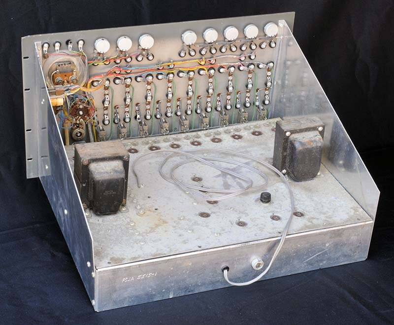
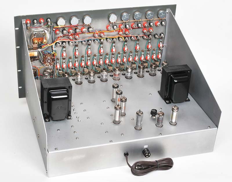
8.5.1 Visual Pre-Power Inspection
  SAFETY FIRST — do NOT apply power until this list is complete.

  □  Tube complement: verify all sockets populated (9× 6U8A, 1× 12BH7A,
       1× 6AQ5, 1× 6BH6, 1× 0A2, 1× 0B2)
  □  Power transformer: inspect for burn marks, cracked varnish, oil stain
  □  Line cord: inspect insulation; replace if rubber is cracked / brittle
       → replace with 3-conductor 16 AWG; bond earth ground to chassis
  □  Fuse: verify correct rating is installed (check assembly manual)
  □  Selenium rectifiers: inspect potted stacks for white powder / burn smell
       → replace with 1N4007 stacks if selenium is present
  □  Electrolytic capacitors: look for bulged tops, brown leakage stains,
       cracked sleeves → replace all before first power-on (see 6.2)
  □  Resistors: check for burn discoloration, cracked bodies
  □  Wiring: look for chafed insulation contacting chassis or transformer core
  □  Tube sockets: check for bent pins, corrosion — clean with DeOxit
  □  Front-panel binding posts: check for green corrosion internally
  □  Patch sockets (27× brown 2-pin): check seating; clean contacts
8.5.2 Capacitor Replacement Priority Table
Table 11 — 6.2 Capacitor Replacement Priority Table
| Location | Type | Original Value | Replacement Spec | Priority |
|---|---|---|---|---|
| +300 V supply filter | Electrolytic | 40 µF / 450 V | 105°C, ≥450 V | Critical |
| −150 V supply filter | Electrolytic | Per schematic | 105°C, ≥200 V | Critical |
| IC supply filter caps | Electrolytic | Per schematic | 105°C, ≥150 V | Critical |
| Amp coupling / bypass | Electrolytic (small) | Per schematic | 105°C, same µF/V | High |
| Feedback capacitors (plug-in) | Mylar / film | 1 µF, 150 V original | 1 µF Mylar, 630 V rated | High |
| Oscillator timing cap | Electrolytic or film | Per schematic | 105°C, same value | Medium |
| High-frequency filter (per amp) | Ceramic disc | 5,600 pF | Same or C0G/NP0 | Low |
Note — Feedback capacitors for the plug-in problem elements should be rated 630 V even though operating voltage is well below that; the elevated rating ensures stability of capacitance with voltage (avoid X5R/X7R ceramics — use film). See Vol 7 (Component Selection) for dielectric recommendations.
8.5.3 Resistor Audit
Table 12 — 6.3 Resistor Audit
| Location | Likely Drift | Test Method | Accept Limit |
|---|---|---|---|
| 1 MΩ precision input/feedback | Carbon comp: up to +30% | DMM out-of-circuit | ±1% (replace with metal-film 1%) |
| 3 kΩ balance pots | Wiper wear, noise | DMM resistance + audio sweep | Replace if scratchy or >5% off |
| 100 kΩ coeff pots | Taper wear | Rotation feel + DMM | Replace if dead spots |
| Wire-wound power resistors | Stable | DMM | ±5% accept |
| 2.2 MΩ positive-feedback R (per amp) | Carbon drift | DMM | ±10% accept (non-critical) |
8.5.4 Tube Testing Order
Table 13 — 6.4 Tube Testing Order
| Priority | Tube | Why |
|---|---|---|
| 1 | 6U8A ×9 | Most critical; bad tube causes amp failure; test emission and Gm |
| 2 | 0A2, 0B2 | VR tubes; test for correct strike/regulation voltage |
| 3 | 12BH7A | Multivibrator; test both triode sections |
| 4 | 6AQ5, 6BH6 | Support roles; test emission |
Tip — NOS Sylvania and GE 6U8A are preferred. Test each section of the 6U8 separately (pentode section Gm, triode section emission). A tube can pass on one section and fail on the other.
8.6 EC-1 Field Cheatsheet — Panel 7: Troubleshooting Quick-Triage
8.6.1 Symptom-to-Cause Decision Tree
  SYMPTOM: Computer does not power on
  ──────────────────────────────────────────────────────────────────────────
  → FILAMENT lamp off?
      YES → check line cord, fuse, FILAMENT switch continuity
      NO  → FILAMENT on but HIGH VOLTAGE lamp off?
            YES → interlock fault; FILAMENT switch must be ON first;
                  check interlock wiring from FILAMENT to HV switch
            NO  → proceed

  SYMPTOM: 0A2 or 0B2 does not glow after warm-up
  ──────────────────────────────────────────────────────────────────────────
  → Replace VR tube first (cheap, common failure)
  → If new tube still dark: check B− rectifier diode, filter cap, B− rail
  → Measure −150 V rail: should be −150 ±5 V. Unregulated (> −160 V) → bad cap
  → Measure IC supply rail: should be ~108 V. Low → 0B2 failed or cap open

  SYMPTOM: Amplifier will not null (balance) / output drifts
  ──────────────────────────────────────────────────────────────────────────
  → Is balance pot at end of travel?
      YES → 6U8A tube suspect; replace
      NO  → check balance pot for noise (crackle when adjusted) → replace 3 kΩ pot
  → Is B+ exactly +300 V? (check SET B+ meter position)
      NO  → adjust VC trim; if trim is at end of range, check filter caps, rectifier
  → Check all 9 amps; if only one fails: isolated tube or pot failure
  → If all 9 fail simultaneously: power supply problem (B+, B−, or heater)

  SYMPTOM: Amplifier output saturates (pegged ±60 V) during MANUAL run
  ──────────────────────────────────────────────────────────────────────────
  → Check amplitude scaling (problem variable exceeds 60 V)
  → Verify initial condition polarity and magnitude (IC supply correctly grounded?)
  → Check integrator relay contacts: are they wired across feedback cap?
      NO  → cap retains charge from prior run, causing false initial condition
  → Check that OPERATION was in RESET before switching to MANUAL

  SYMPTOM: REPETITIVE mode unstable / erratic cycling
  ──────────────────────────────────────────────────────────────────────────
  → 12BH7A tube suspect; replace both triode sections
  → Check oscillator timing capacitor (electrolytic may have dried)
  → Check relay coil continuity; relay contacts for arcing or welded contacts
  → Verify OPERATION switch at REPETITIVE (not MANUAL)

  SYMPTOM: 60 Hz hum on amplifier output(s)
  ──────────────────────────────────────────────────────────────────────────
  → IC supply common-mode hum coupling into op-amp inputs
      → add small isolation transformer under chassis in IC supply line
      → verify IC supply ground: one terminal must be grounded before use
  → Check heater wiring routing; heater leads near signal nodes inject hum
  → Check filter capacitors on B− rail (dried cap → ripple on −150 V)
  → If hum on all amps equally: B+ supply filter cap(s) drying out

  SYMPTOM: Meter pegs on amplifier read-out selection
  ──────────────────────────────────────────────────────────────────────────
  → Set METER RANGE to 100 V before switching FUNCTION to any AMP position
  → If all amps peg: amplifiers not balanced; redo balance sequence
  → If one amp pegs: isolated failure on that amp (tube, patch wiring error)

  SYMPTOM: Relay contacts do not open in MANUAL mode
  ──────────────────────────────────────────────────────────────────────────
  → 6AQ5 relay driver tube failed (open plate)
  → Relay coil open — check continuity with power off, caps discharged
  → OPERATION switch contact dirty — clean with DeOxit
8.6.2 Voltage Reference Table (normal operation)
Table 14 — 7.2 Voltage Reference Table (normal operation)
| Test Point | Expected Value | Tolerance | Instrument |
|---|---|---|---|
| B+ rail (+300 V) | +300 VDC | ±10 V | DMM, HV probe |
| B− rail (−150 V) | −150 VDC | ±5 V | DMM, HV probe |
| IC supply output | 0 – +100 VDC | ±2 V at any set point | DMM |
| Heater voltage (6.3 VAC) | 6.3 VAC | ±0.3 V | DMM AC |
| Amp output (balanced, no input) | 0.0 V | ±0.5 V (1 V range) | Meter on front panel |
| 0A2 anode-to-cathode | ~150 V | ±5 V | DMM, HV probe |
| 0B2 anode-to-cathode | ~108 V | ±5 V | DMM, HV probe |
8.6.3 Triage by Amplifier Section
  TOOL NEEDED: tube tester capable of 6U8A (noval, pentode + triode sections)

  If amp N fails:
  ┌─────────────────────────────────────────────────────────────────────┐
  │  Step 1: Swap V_N (6U8A) with a known-good tube from a working amp  │
  │  Step 2: If fault moves with tube → replace tube                     │
  │  Step 3: If fault stays on amp N → check balance pot (3 kΩ)          │
  │  Step 4: Check 2.2 MΩ positive-feedback resistor (per amp circuit)  │
  │  Step 5: Check 1 kΩ + 5,600 pF HF filter network (per amp)          │
  │  Step 6: Check NE-2H neon lamps (2 per amp) — level-shifting element │
  │  Step 7: Trace wiring to that amp's binding posts and plug sockets   │
  └─────────────────────────────────────────────────────────────────────┘
8.7 EC-1 Field Cheatsheet — Panel 8: Safety Card (+300 V / −150 V)
Danger — The Heathkit EC-1 contains lethal DC voltages. The +300 V B+ rail and −150 V B− rail are both capable of causing ventricular fibrillation through skin contact. The initial-condition supplies reach +105 V. Front-panel signal jacks are safe (±60 V signal range) but internal rails are not isolated. Treat all internal nodes as live until individually verified dead with a meter.
8.7.1 Hazardous Voltage Locations
  ┌─────────────────────────────────────────────────────────────────────────┐
  │                   EC-1 INTERNAL VOLTAGE MAP                             │
  │                                                                         │
  │   AC Mains (105–125 VAC)                                                │
  │       │                                                                 │
  │       ▼                                                                 │
  │   Power transformer primary ── [LINE CORD] ── FILAMENT SW ── HV SW     │
  │       │                                                                 │
  │       ├── 6.3 VAC secondary ──► tube heaters (all)        ← LOW risk   │
  │       │                                                                 │
  │       ├── HV secondary ──► rectifier ──► +300 VDC ─────── ◄ LETHAL ►  │
  │       │                   filter caps (hold charge after off)           │
  │       │                                                                 │
  │       └── −HV secondary ──► rectifier ──► −150 VDC ────── ◄ LETHAL ►  │
  │                                           (0A2 regulated)               │
  │                                                                         │
  │   IC Supplies (×3):  0 – +105 VDC ──────────────────────── ◄ SERIOUS► │
  │                      (0B2 regulated; floating, not grounded)            │
  │                                                                         │
  │   Front-panel signal jacks: ±60 VDC max ──────────────────── moderate  │
  │   (still enough for painful shock; avoid prolonged contact)             │
  └─────────────────────────────────────────────────────────────────────────┘
8.7.2 Safety Rules — Non-Negotiable
Table 15 — 8.2 Safety Rules — Non-Negotiable
| # | Rule |
|---|---|
| 1 | Never work inside the chassis with power applied. Make measurements with a long-lead DMM; keep one hand in pocket or behind back. |
| 2 | Wait ≥ 60 s after power-off before opening chassis. Filter capacitors at +300 V may retain charge for several minutes through high-value bleeder resistors. |
| 3 | Verify voltages are down with a DMM (600 V CAT II or better) before touching any internal node. Check both +300 V and −150 V rails. |
| 4 | Do not defeat interlocks. The HV switch requires the FILAMENT switch to be ON; this sequencing protects the rectifier tube and limits inrush. |
| 5 | Use insulated probes only. Clip leads with bare metal jaws must not be used near B+ rails. Use fully shrouded probes and alligator clips. |
| 6 | Ground the chassis. Ensure the earth-ground conductor of the replacement 3-conductor line cord is bonded to the steel chassis. Verify continuity with DMM before power-on after any rewiring. |
| 7 | IC supplies are floating. One terminal must be grounded before connection to the problem board. Floating supplies can develop hazardous common-mode voltage relative to chassis. |
| 8 | Front-panel jacks are not safe to touch under power. Signal outputs reach ±60 V; that is below the commonly cited 100 V “safe” threshold but can still cause cardiac event in persons with heart conditions or wet hands. Use patch cords with shrouded banana plugs. |
| 9 | Capacitor discharge. After power-off, if rapid chassis entry is required, manually discharge filter capacitors through a 10 kΩ, 10 W resistor connected briefly across B+ to chassis ground and B− to chassis ground. |
| 10 | Selenium rectifier note. If original selenium rectifiers are present, they may emit toxic selenium dioxide fumes when failing. Work in a ventilated area; replace with silicon 1N4007 equivalents before sustained operation. |
8.7.3 Emergency Procedures
  ELECTRIC SHOCK:
  □ Do NOT touch the victim if they are still in contact with the source.
  □ Switch off power at the wall or pull the line cord first.
  □ Call emergency services (911 / local equivalent) immediately.
  □ If victim is unresponsive and not breathing, begin CPR.
  □ AED if available: even low-probability fibrillation from >50 V contact
    warrants cardiac evaluation.

  FIRE / SMOKE:
  □ Power off immediately (line cord or wall breaker).
  □ CO2 or dry-powder extinguisher only — never water on energized equipment.
  □ If selenium rectifier is burning: evacuate room; selenium dioxide is toxic.
  □ Allow chassis to cool before re-entering if selenium smoke was present.

  CAPACITOR FAILURE / EXPLOSION:
  □ Electrolytic cap rupture ejects electrolyte. Avoid eyes.
  □ Power off; ventilate; allow 15 min before inspection.
  □ Wear safety glasses when applying power to a newly-recapped unit for the
    first time — use variac, stand back, and monitor from a distance.
8.7.4 PPE and Tools Minimum Kit for EC-1 Work
Table 16 — 8.4 PPE and Tools Minimum Kit for EC-1 Work
| Item | Specification |
|---|---|
| DMM | 600 V CAT II or CAT III; auto-ranging with over-range alarm |
| HV probe | 40 kV rated; use for high-confidence B+ measurements |
| Safety glasses | ANSI Z87.1; required during capacitor formation / first power-on |
| Discharge resistor | 10 kΩ, 10 W WW on insulated leads; for manual cap discharge |
| Variac | 0–140 VAC, ≥2 A; mandatory for first power-on of unrestored unit |
| Insulated probes | Fully shrouded; IEC 61010-031 compliant |
| Work mat | Anti-static, insulating; keep chassis elevated off bare metal bench |
Note — The variac ramp-up procedure for capacitor reformation: start at 10 VAC; raise 10 V per minute while monitoring current draw and sniffing for smoke. If current spikes or smoke appears, lower immediately. Full voltage should be reached only after all electrolytic capacitors have been either replaced or reformed without incident. See Vol 4 (Acquisition & Restoration) for the full variac protocol.
8.8 Quick Cross-Reference to Other Volumes
Table 17 — Quick Cross-Reference to Other Volumes
| Topic | Volume |
|---|---|
| EC-1 history, specifications, physical overview | Vol 1 (Overview & History) |
| Hardware, power supply circuits, +300 V / −150 V design, op-amp circuit internals | Vol 2 (Hardware & Theory of Operation) |
| Patch panel, computing elements, IC supplies, relay contacts | Vol 3 (Patch Panel & Computing Elements) |
| Acquisition, restoration procedures, BOM, variac protocol | Vol 4 (Acquisition & Restoration) |
| Programming methodology, scaling, problem setup | Vol 5 (Programming) |
| Sample programs (SHM, damped oscillator, projectile, bouncing ball) | Vol 6 (Sample Programs & Demonstrations) |
| Oscilloscope interfacing, data-logging, solid-state substitution | Vol 7 (Modern Extensions & Interfacing) |
Comments (0)