Heathkit EC-1 · Volume 4
Heathkit EC-1 — Volume 4 — Acquisition & restoration
How to find, evaluate, strip, recap, retube, and bring up a working EC-1 — prerequisites for Vol 5 (programming) and Vol 6 (advanced demos)
The EC-1 is a 43-pound, 100-watt vacuum-tube instrument with internal voltages reaching +300 VDC and −150 VDC. Its age — the last units shipped from Benton Harbor, Michigan, in 1971 — guarantees that every surviving chassis requires at minimum a careful inspection and capacitor audit before any power-up. This volume provides a repeatable acquisition and restoration workflow derived from the original Heathkit Assembly Manual and Operational Manual, the Nuts & Volts restoration article by David Goodsell (May 2016), and the circuit analysis in Vol 2 of this series.
Danger — High Voltage. Internal bus voltages reach +300 VDC and −150 VDC. A charged 100 µF filter capacitor at 300 V stores 4.5 joules — sufficient to cause cardiac arrest. Always discharge the main filter bank through a 10 kΩ / 10 W bleeder before probing chassis wiring, and treat every contact point as live until confirmed dead with a meter.
4.1 About this Volume
This volume covers the practical aspects of acquiring and restoring an EC-1 to full operating condition. The sequence follows the recommended bring-up order from the official Assembly Manual: power supplies verified first, then operational amplifiers, then control circuits, and finally the front panel and patch board. Circuit theory is intentionally brief here; see Vol 2 for DC op-amp architecture and the repetitive-operation control circuit. Vol 3 covers the patch panel and computing elements. Vol 5 covers first-problem programming once the machine is verified live.
The documented Nuts & Volts restoration (purchased $420 on eBay, 2016) serves as the primary real-world reference throughout. Where that restoration diverges from factory practice, both paths are noted.
4.2 Finding One — Marketplaces, Networks, and Hamfests
4.2.1 Market Channels
The EC-1 is rare but not unobtainable. Fewer than a few thousand were assembled between 1959 and 1971, and surviving units skew toward academic surplus and ham-radio estates. Regular monitoring of several channels simultaneously is the most efficient acquisition strategy.
Table 1 — Market Channels
| Channel | Typical Ask | Notes |
|---|---|---|
| eBay (US) | $420 – $1,500 | Most liquid market; units appear irregularly. Search “Heathkit EC-1” and “Heathkit analog computer”. Monitor saved-search alerts. |
| eBay Canada | CAD $550 – $1,600 | Cross-border shipping adds cost; inspect photos carefully before bidding. |
| Craigslist / Facebook Marketplace | $200 – $800 | Local-pickup units appear occasionally in university towns and coastal metro areas. Often priced by sellers who do not know what they have. |
| Vintage Computer Federation (VCF) Forums | Varies | Active community swap/wanted section at forum.vcfed.org. Posting a “wanted” ad is free and reaches knowledgeable sellers. |
| Hamfests / ARRL events | $50 – $400 | Historically the lowest-price source; units surface in ham-radio estates. Use the ARRL Hamfest Calendar at arrl.org to find regional events. |
| Collector donations | Free | Mark Garlanger actively solicits EC-1 donations ([email protected] / heathkit.garlanger.com/wanted/). System Source Computer Museum (Hunt Valley, MD) and Rhode Island Computer Museum may know of available duplicates. |
| Antique Radio Classifieds | Occasional | antiqueradio.org/classifieds.php targets hobbyists likely to price fairly. |
Price band analysis. The documented acquisition at $420 (Goodsell, 2016) represents a lower bound for a complete but heavily degraded unit. Cosmetically clean, partially working units routinely exceed $800. A fully restored and tested unit with patch cords and documentation may reach $1,200–$1,500. Budget separately for restoration consumables (see Section 4).
4.2.2 Pre-Purchase Remote Inspection Checklist
Before bidding or buying sight-unseen, request photos that answer every item on the following checklist. A seller who cannot provide interior photos should be considered as selling an unknown.
Table 2 — Pre-Purchase Remote Inspection Checklist
| Item | What to Look For | Red Flag |
|---|---|---|
| Front panel silk-screen | Clean legends; all nine balance-pot labels readable | Scratches through the legend — nearly impossible to repair authentically |
| Binding posts | Red/black visible; not deeply corroded | Missing posts indicate prior parts-stripping |
| 27 two-pin brown crystal sockets | All present; none cracked | Missing or broken sockets are nearly irreplaceable (surplus-sales.com #EBY-HC6, often out of stock) |
| Tube complement | 17 tubes visible in sockets | Missing tubes — common; replaceable but adds cost |
| Power transformer | No burn marks, no smell described | Burned primary windings render unit uneconomical to restore |
| Chassis interior | Visible corrosion level, wiring condition | Standing water stains or severe rust on chassis rails |
| Cabinet | Light surface rust acceptable | Deep pitting or structural deformation |
| Original patch cords | 27 two-pin plug assemblies | Missing — common; fabrication is a sub-project (see Section 5) |
| Operational manuals | Originals add value | Freely downloadable from archive.org and analogmuseum.org |
Tip — Calibration stickers. Any calibration or inventory stickers affixed directly to the aluminum front panel will leave a discolored ghost when removed. Factor this into cosmetic assessment.
4.3 Pre-Power-Up Procedure
4.3.1 Visual Inspection Protocol
Before connecting power, spend 30–60 minutes on a thorough visual inspection with the chassis on a clean workbench under good lighting. This inspection governs which restoration path to follow.
VISUAL INSPECTION DECISION TREE
────────────────────────────────────────────────────────────
Power transformer: burn marks or smell?
       YES → Measure primary/secondary resistance before proceeding.
              If open winding → unit may not be economical to restore.
       NO  ↓
Selenium rectifiers present (potted stack, dark brown/gray)?
       YES → Plan immediate replacement with 1N4007 silicon diodes.
       NO  ↓
Electrolytic capacitors: bulging, leaking, or >30 years old?
       YES (always true for a 50-year-old unit) → Full recap (Section 4).
       NO  → Unlikely; recap anyway.
Wafer switch contacts: visibly corroded?
       YES → Clean with silver cleaner; do not bend contacts.
       NO  ↓
Tube sockets: pin contact visible corrosion?
       YES → Clean with DeOxit; consider replacement if severe.
       NO  ↓
OK to proceed to dim-bulb test and reform sequence.
────────────────────────────────────────────────────────────
4.3.2 Dim-Bulb Tester
A dim-bulb tester — a standard incandescent lamp in series with the AC line — is the safest first power application. A 60-watt bulb limits inrush current to approximately 0.5 A and will glow brightly if any catastrophic fault (shorted filter cap, failed rectifier, shorted winding) is present.
        FUSED                 DIM-BULB
        PLUG                  TESTER
  ┌──── HOT ────[FUSE 2A]────[60W LAMP]────┐
  │                                         │ TO EC-1
  └──── NEUTRAL ───────────────────────────┘ POWER INLET
Procedure:
- Remove all tubes before the dim-bulb test; this isolates the passive power-supply network.
- Connect the dim-bulb tester in series with the EC-1 line cord.
- Apply AC power. The lamp should glow dimly for approximately 2 seconds (charging the filter caps), then extinguish or go very dim.
- If the lamp stays bright: a fault is present. Isolate by disconnecting the B+ and B− secondaries one at a time.
- If the lamp extinguishes: the passive power network is not shorted. Proceed to capacitor reform or replacement.
Danger — Charged Capacitors After Dim-Bulb Test. Even with a series lamp, the filter capacitors will charge to line-derived voltages. After removing AC power, short each electrolytic terminal pair through a 10 kΩ / 10 W resistor and confirm with a meter before touching any internal node.
4.3.3 Capacitor Reforming vs. Replacement
The EC-1 contains a mix of large electrolytic filter capacitors and smaller signal-path electrolytics. After 50+ years, all electrolytic capacitors should be considered suspect regardless of visual appearance.
Reforming (applying DC voltage gradually via a variac and series resistor) can sometimes recover electrolytics that have merely lost their oxide layer due to long storage. The procedure — raising voltage from 0 to rated in 10% steps, holding 30 minutes at each step — is time-consuming and unreliable for capacitors of this age. The Goodsell restoration elected to replace all electrolytics rather than reform, which is the recommended approach for any restoration intended for regular use.
The Goodsell technique for large cans: Slip new capacitors inside the original paper sleeves to preserve the vintage appearance. The new capacitor body must have a smaller diameter than the sleeve’s inner bore; most modern axial electrolytics are slim enough to fit inside the original 1-inch-diameter Heathkit sleeves.
Note — Reforming vs. Replace Decision. Museum-preservation restorations that must retain original parts may prefer a slow-reform protocol. Working-instrument restorations intended for regular use should replace all electrolytics. The original parts can be retained in a parts bag for provenance.
4.4 Recapping — Bill of Materials
The following tables cover every electrolytic and paper/wax capacitor in the EC-1. Values are drawn from the original Assembly Manual Parts List and Schematic. Modern replacement part numbers are from Digi-Key and Mouser as of 2025; verify availability before ordering.
4.4.1 Electrolytic Capacitors — Main Power Supply and Amplifier Decoupling
Table 3 — Electrolytic Capacitors — Main Power Supply and Amplifier Decoupling
| Ref | Original Value | Original Voltage | Modern Replacement | Digi-Key Part No. | Qty | Supplier |
|---|---|---|---|---|---|---|
| C1 (main B+ filter) | 40 µF | 450 V | 47 µF 450 V axial | P5542-ND | 1 | Digi-Key |
| C2 (main B+ filter, second section) | 40 µF | 450 V | 47 µF 450 V axial | P5542-ND | 1 | Digi-Key |
| C3 (−150 V filter) | 20 µF | 200 V | 22 µF 200 V axial | P5536-ND | 1 | Digi-Key |
| C4, C5, C6 (IC supply filters) | 20 µF | 150 V | 22 µF 160 V axial | P13453-ND | 3 | Digi-Key |
| C7–C15 (per-amplifier bypass, one per 6U8) | 10 µF | 50 V | 10 µF 63 V radial | 493-1106-ND | 9 | Digi-Key |
| C16 (multivibrator timing) | 2 µF | 50 V | 2.2 µF 63 V radial | 493-1096-ND | 1 | Digi-Key |
Note — Voltage Rating. Always use a replacement rated at the same voltage or higher. For the +300 V supply filter bank, 450 V-rated parts provide an appropriate margin; 400 V-rated parts are marginal and not recommended.
4.4.2 Paper, Wax, and Mylar Signal-Path Capacitors
Table 4 — Paper, Wax, and Mylar Signal-Path Capacitors
| Ref | Original Value | Type | Modern Replacement | Digi-Key Part No. | Qty | Notes |
|---|---|---|---|---|---|---|
| Cf (integrator feedback, per socket) | 1 µF | Paper/mylar | 1 µF 100 V polyester film | 399-4151-ND | 9 | One per amp; mount on plug assemblies |
| High-voltage simulation caps (bouncing ball) | 1 µF | Paper, 630 V | 1 µF 630 V polypropylene | C-FS-630-1MFD (AES) | 4–5 | From Antique Electronic Supply (tubesandmore.com) |
| C4 (multivibrator coupling) | 0.1 µF | Ceramic/mylar | 0.1 µF 50 V ceramic | (verify p/n — e.g. Digi-Key 1µF/0.1µF film) | 1 | |
| HF filter caps (5600 pF, per amplifier) | 5600 pF | Ceramic disc | 5600 pF 100 V ceramic | 399-9727-ND | 9 | Part of high-frequency rolloff network in each op-amp |
Note — Part numbers are representative — verify current stock/specs before ordering.
4.4.3 Summary — Full Recap BOM
Table 5 — Summary — Full Recap BOM
| Category | Quantity | Approximate Cost (2025) |
|---|---|---|
| Main filter electrolytics (450 V) | 2 | $8–$12 |
| B− filter electrolytic (200 V) | 1 | $3–$5 |
| IC supply filters (160 V) | 3 | $6–$9 |
| Per-amplifier bypass (63 V) | 9 | $5–$8 |
| Timing / coupling electrolytics | 2 | $3–$5 |
| Mylar integrator capacitors | 9 | $12–$18 |
| High-voltage simulation caps (630 V) | 5 | $18–$25 (AES) |
| HF filter ceramics | 9 | $4–$7 |
| Total estimated | $59–$89 |
Supplier contacts: Digi-Key (digikey.com), Mouser Electronics (mouser.com), Antique Electronic Supply / TubesAndMore (tubesandmore.com).
4.5 Tubes — Complement, Testing, Sourcing, and Substitutions
4.5.1 Complete Tube Complement
The EC-1 uses 17 vacuum tubes total. The original Assembly Manual lists the following:
Table 6 — The EC-1 uses 17 vacuum tubes total. The original Assembly Manual lists the following
| Tube Type | Quantity | Function | Socket Type |
|---|---|---|---|
| 6U8 (triode-pentode) | 9 | DC operational amplifier (one per amp) | 9-pin noval (B9A) |
| 12BH7 (dual triode) | 1 | Repetitive oscillator / multivibrator | 9-pin noval (B9A) |
| 6AQ5 (beam tetrode) | 1 | Relay driver / power stage | 7-pin miniature (B7G) |
| 6BH6 (pentode) | 1 | Control circuit function | 7-pin miniature (B7G) |
| 0A2 (VR tube, 150 V) | 1 | Voltage regulator, −150 V supply reference | 7-pin miniature (B7G) |
| 0B2 (VR tube, 108 V) | 1 | Voltage regulator, IC supply reference | 7-pin miniature (B7G) |
| NE-2H (neon lamp) | 18 | Level-shift elements in op-amp output stage (2 per amp) | Wire-lead, mounted on socket |
Note — VR Tube Glow. The 0A2 and 0B2 are cold-cathode voltage-regulator tubes. Both produce a distinctive purple-blue glow discharge during normal operation. A tube that fails to illuminate after 60–90 seconds of warm-up with correct B+ applied is defective. Do not confuse the 0A2 (150 V regulation, used for the −150 V supply) with the 0B2 (108 V regulation, used for the IC supplies); they are not interchangeable despite similar appearance.
4.5.2 The 6U8 Operational Amplifier Tube
The 6U8 is the most critical and most numerous tube in the EC-1. Its pentode section, operated with a reduced screen voltage (approximately 55 V), provides the bulk of the open-loop gain (~700×); the triode section forms the cathode-follower output stage. A 2.2 MΩ positive-feedback resistor raises total gain to approximately 1,000. Two NE-2H neon lamps per amplifier perform level-shifting in the output.
Gain of exactly 1,000 is not critical — the heavy negative feedback of the computing configuration (Rf/Ri ratios of 1–100) swamps tube-to-tube variation. What matters is that each tube is not gassy, not microphonic, and biases to a stable quiescent point.
Testing the 6U8: A mutual-transconductance tube tester (Hickok 752, 800, TV-7, or equivalent) should read the pentode section at ≥2,500 µmhos and the triode section at ≥1,600 µmhos. Reject any tube reading below 70% of rated Gm or showing gas.
4.5.3 Tube Sourcing and Substitutions
Table 7 — Tube Sourcing and Substitutions
| Tube | Availability | NOS Sources | Substitute |
|---|---|---|---|
| 6U8 | Moderate | AES, VIVA Tubes, Tube World Express | ECF82 (European equivalent, pin-compatible; verify socket numbering) |
| 12BH7 | Good | AES, eBay, VacuumTubes.net | 12BH7A (direct replacement) |
| 6AQ5 | Excellent | Widely available; GE, RCA, Sylvania NOS common | 6005, EL90 (pin-compatible) |
| 6BH6 | Good | eBay, VacuumTubes.net | 6BC5, 6BE6 (functional equivalents — verify pin-out) |
| 0A2 | Good | AES, specialty VR tube dealers | Cannot use 0B2; 1N4761A 75 V Zener for the IO-10 companion scope only |
| 0B2 | Good | AES, specialty VR tube dealers | Cannot use 0A2; no direct solid-state substitute for −150 V reference |
| NE-2H | Good | Mouser, Newark, AES | NE-2 (same electrical; verify lead spacing) |
Tip — Buy Nine 6U8 Tubes. The standard restoration recommendation is to purchase a complete set of nine matched or at-minimum tested 6U8s from a single lot. Mixed brands from different eras can produce balance-pot settings that differ so widely between amplifiers that the balance trim range is consumed before zero-null is achieved.
4.5.4 Tube Socket Condition
The EC-1 uses two types of sockets: 9-pin noval wafer sockets and 7-pin miniature wafer sockets. The wafer-type contacts contain custom wiper elements that would be extremely difficult to replicate if broken. Recommended procedure:
- Wick solder cleanly from each lug before removing wires.
- Clean socket contacts with a cotton swab dampened in DeOxit D100 (full-strength), not spray contact cleaner (which leaves residue in wafer layers).
- Lightly tarnished contacts that are structurally sound: clean and reuse.
- Heavily corroded or cracked sockets: replace with wafer-type noval (9-pin) or miniature (7-pin) sockets from AES (tubesandmore.com).
4.6 Cabinet Refinishing — Panel and Silk-Screen Care, Repaint
4.6.1 The Original Finish
The EC-1 cabinet is a two-piece steel enclosure — a lower chassis pan and upper rear cover — finished from the factory in a gray wrinkle-finish lacquer. The front panel is a separate aluminum plate with silk-screened legends in gray and white. These two substrates require completely different treatment.
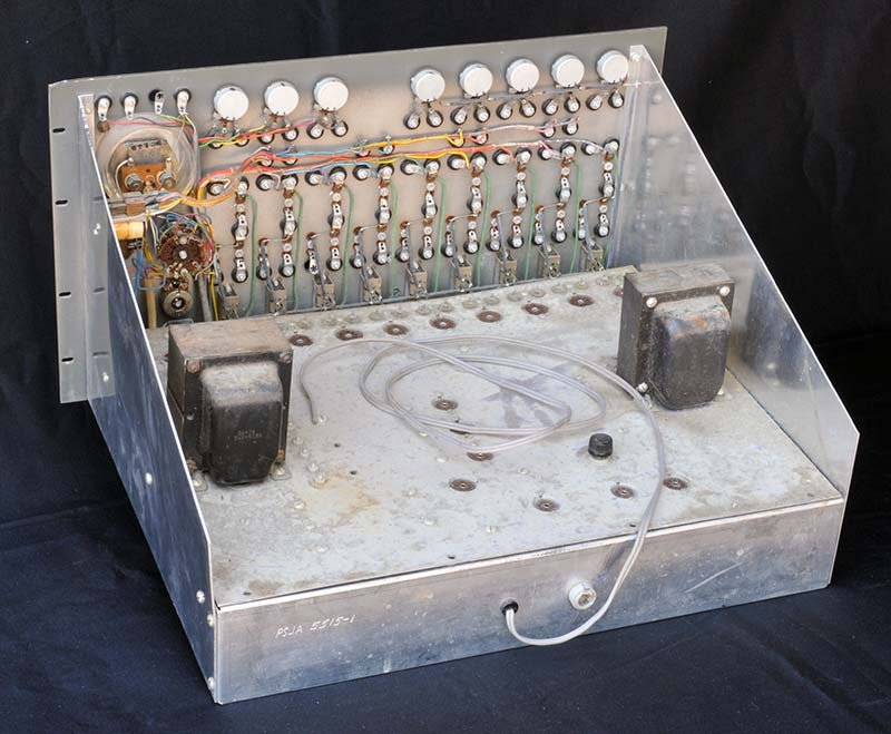
The chassis interior prior to restoration. Note the original paper-sleeved electrolytic capacitors, selenium rectifier stack, and surface corrosion on the aluminum chassis rails. Reproduced courtesy Nuts & Volts / David Goodsell (May 2016).
4.6.2 Aluminum Front Panel — Handle with Extreme Care
Danger — Irreplaceable Silk-Screen. The front-panel silk-screened legends are printed directly on the anodized aluminum and cannot be authentically reproduced without photographic masking and silk-screen facilities. Any abrasive contact — sandpaper, steel wool, abrasive cleaners — will destroy the legends permanently. A single scratch through a label devalues the instrument significantly for the collector community.
Cleaning procedure (front panel only):
- Remove all binding posts and controls before cleaning.
- Dampen a lint-free cloth with 70% isopropyl alcohol. Do not use acetone, MEK, lacquer thinner, or any petroleum solvent on the painted/silk-screened surface.
- Wipe gently with the grain of any brushing in the aluminum.
- For stubborn grime in recesses around controls, use a wooden toothpick — never a metal probe.
- Allow to fully dry before reassembly.
If the silk-screen is damaged: A skilled sign shop can produce vinyl-cut overlays from high-resolution scans. The Heathkit Virtual Museum (heathkit-museum.com) and the Computer History Museum collection both hold high-quality images of the EC-1 front panel. The overlay approach is visible on close inspection but acceptable for a working instrument.
4.6.3 Aluminum Chassis Panels
The inner aluminum chassis panels (not the steel outer cabinet) commonly develop surface corrosion from decades of humidity exposure.
- Use a small handheld orbital sander (fine grit, 220) to level corrosion spots.
- Finish with a green abrasive kitchen pad (Scotch-Brite or equivalent) using circular motion — this imparts a consistent brushed-aluminum luster that hides minor scratches and abrasion marks.
- Do not anodize or clear-coat; leave bare aluminum, which forms a stable passive oxide layer.
4.6.4 Steel Outer Cabinet — Refinishing Options
The steel outer shell (not the aluminum front panel) is the target for paint refinishing. Three documented approaches are available:
Table 8 — The steel outer shell (not the aluminum front panel) is the target for paint refinishing. Three documented approaches are available
| Option | Material | Source | Result | Notes |
|---|---|---|---|---|
| A — Gray Wrinkle Spray | VHT Wrinkle Plus, gray | AutoZone, O’Reilly, NAPA | Closest to original texture | Activate wrinkle with heat gun at 150–180 °C; exact gray shade may vary slightly from original |
| B — Gray Hammertone Powder Coat | Professional powder coat | Local powder coat shop | ”Looks great and tough as nails” (Goodsell) | Most durable; requires professional equipment; cannot be done at home |
| C — Custom Color Match | Sherwin-Williams scan-matched | Paint dealer with electronic color scanner | Near-exact original match | Ask for hammertone or texture base; bring original cabinet section for scanning |
Cabinet preparation (all options):
- Remove all hardware, rubber grommets, and the front panel assembly.
- Sand rust spots: 120-grit to remove scale, 220-grit to smooth.
- Apply self-etching primer to all bare metal areas.
- Degrease thoroughly with acetone or MEK immediately before painting.
- Mask the front panel opening completely; no paint on aluminum.
Tip — Rubber Grommets. All chassis cable-routing holes use rubber grommets that become brittle and crack with age. Replace every grommet as a matter of course — approximately 20 assorted sizes. Hardware stores (McMaster-Carr, Grainger) and Digi-Key carry assorted grommet kits. New pliable grommets make a surprisingly large cosmetic difference on a freshly painted chassis.
4.6.5 Binding Posts
The EC-1 front panel carries a large number of red and black banana binding posts. After 50+ years, the internal contact springs corrode and tarnish, producing high-resistance connections that directly degrade computing accuracy. The Goodsell restoration found one post missing and the remainder internally tarnished; the decision was made to replace all posts with a single order of six dozen new units.
Replacement binding posts: Standard 4 mm banana binding posts in red and black are available from Digi-Key (part families: 5017 series, Keystone Electronics), Mouser, and eBay. Verify that the thread diameter and panel-hole diameter match the EC-1 panel holes (nominal 3/8” for binding-post bodies) before ordering.
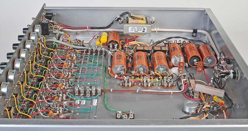
The rewired chassis showing the five parallel bus bars that distribute +300 VDC, −150 VDC, and 6.3 VAC heater voltage to all nine operational amplifiers. New binding posts, wafer tube sockets, and rubber grommets are visible throughout. Reproduced courtesy Nuts & Volts / David Goodsell (May 2016).
4.7 Bring-Up and Amplifier Balancing Procedure
4.7.1 Power-Supply Bring-Up Sequence
The official assembly and operational manuals prescribe a power-supply-first bring-up sequence. This is not merely convention: the op-amp circuits depend on regulated rails being present before signal connections are active. Connecting the op-amps to unregulated or wrong-polarity rails can permanently damage the 6U8 tubes.
Required instruments:
- DC voltmeter, 1 kV range (or DMM with 1 kV CAT II rating)
- 10× oscilloscope probe rated for 600 V
- 50-0-50 µA panel meter (built-in to EC-1)
- Variac (0–140 VAC adjustable autotransformer), 5 A minimum
Step 1 — Initial filament warm-up.
Insert all tubes. Connect the variac to the EC-1 line input. Set the variac to 0 V. Switch FILAMENT on, HIGH VOLTAGE off. Slowly raise the variac from 0 to 120 VAC over approximately 2 minutes, watching for smoke or burning smell at each step. Allow filaments to warm for a minimum of 30 minutes before applying high voltage. This slow-start practice further reforms any marginal electrolytic capacitors.
Step 2 — B+ Verification.
With OPERATION switch in RESET, raise HIGH VOLTAGE. Locate VC (the B+ adjustment trimmer on the chassis rear rail — a 250 kΩ wirewound pot). Set the METER FUNCTION switch to SET B+. Adjust VC until the front-panel meter pointer aligns with the red SET B+ mark, indicating +300 VDC on the positive bus. Measure the B+ bus directly with a voltmeter as a cross-check; the reading should be 295–305 VDC.
Step 3 — B− Verification.
Measure the −150 V bus (black wire on the OA2/OB2 regulator output). Expected: −150 VDC ± 5 V. The OA2 VR tube should show a distinctive purple glow. If the tube does not strike after 60 seconds, check its socket contacts and replace the tube.
Step 4 — IC Supply Verification.
Three ungrounded initial-condition power supplies use OB2 VR tubes as references. Set each IC control to mid-range (approximately 50 V). Measure between the red and black binding posts of each IC supply; the meter should read approximately 50 VDC. Each supply should deliver 0–105 VDC at up to 5 mA.
Step 5 — Heater Voltage.
Measure the 6.3 VAC heater bus (best measured at a 6U8 socket pin 4 or pin 5 to chassis ground AC). Expected: 6.0–6.6 VAC. Significant deviation indicates a wiring fault or a problem with the heater winding.
EC-1 POWER DISTRIBUTION TREE
══════════════════════════════════════════════════════════════

 120 VAC ──[S1 FILAMENT]──────────────────────────► 6.3 VAC bus
          │                                           (all 17 tube heaters)
          └──[S2 HIGH VOLTAGE]──[T1 Power Transformer]
                                    │
                          ┌─────────┴─────────────────────┐
                          │                               │
                   [B+ Rectifier]                  [B- Rectifier]
                   [Electronic Reg.]               [OA2 VR Tube]
                   [VC 250kΩ trim]                      │
                          │                        -150 VDC bus
                   +300 VDC bus                    (op-amp −V rail)
                   (op-amp +V rail)
                          │
                   ┌──────┴──────────────────────────────┐
                   │                                     │
            [IC Supply 1]                        [IC Supply 2] [IC Supply 3]
            [OB2 VR Tube]                        [OB2 VR Tubes]
            [0–105 VDC out]                      [0–105 VDC out each]

══════════════════════════════════════════════════════════════
4.7.2 Amplifier Balancing Procedure
With all four supply rails verified within specification, the nine operational amplifiers can be balanced. The EC-1 provides a dedicated BALANCE circuit: a slide switch below each amplifier’s binding posts disconnects the amplifier from the patch board and connects a 1 MΩ feedback resistor and 1 MΩ input-to-ground resistor, placing each amplifier in unity-gain inverting configuration with a shorted input. The balance pot (3 kΩ) adjusts the output to zero.
Procedure (from the Operational Manual, Section: General Operating Instructions):
- Set OPERATION switch to RESET.
- Set METER FUNCTION to AMPLIFIER BALANCE.
- Set METER RANGE to 100 V.
- For each amplifier 1 through 9:
- Press the balance slide switch downward (disconnects patch board).
- Rotate the AMPLIFIER BALANCE CONTROL (screwdriver slot, or knob if replaced) until the meter reads zero.
- Repeat the entire sequence with METER RANGE at 10 V.
- Repeat again with METER RANGE at 1 V.
Three-pass balancing from 100 V to 1 V range achieves better than ±0.1 V null at each amplifier output — equivalent to 0.17% full-scale error at ±60 V output.
Tip — Pot Replacement. The Goodsell restoration found that the original 3 kΩ balance pots had drifted to as low as 2,150 Ω after 50+ years, and several lacked sufficient range to achieve zero null. Replacement with modern 3 kΩ wirewound or cermet trimmers restores full balance range. The restoration installed pots with knob shafts rather than screwdriver slots; a small cosmetic deviation from original that substantially improves usability.
Amplifier balance verification after patching:
The balance should be checked before each problem run. The slide switches allow balancing with computing components already inserted in the patch board — the switch physically disconnects the amplifier input from the socket bus.
AMPLIFIER BALANCE CIRCUIT (per amplifier)
─────────────────────────────────────────────────────────
                    ┌──1 MΩ (Rf, balance mode)──┐
                    │                           │
BALANCE SW (down) ──┤ ←──1 MΩ to ground (Ri)   │
                    │                           │
                   [6U8 pentode + cathode       │
                    follower output stage]      │
                    │                           │
                    │   3 kΩ balance pot        │
                    │   (cathode bias trim) ────┘
                    │
                   OUT (to front panel binding post)
─────────────────────────────────────────────────────────
4.7.3 Post-Bring-Up Verification
After all nine amplifiers balance cleanly:
-
Configure one amplifier as an inverter: 1 MΩ input resistor plug, 1 MΩ feedback resistor plug.
-
Apply +10 VDC from IC Supply 1 to the amplifier input.
-
The output should read −10.0 ± 0.5 VDC on the front-panel meter.
-
Repeat for all nine amplifiers. Any amplifier that cannot deliver −10 V ± 5% with a balanced null and correct components has a tube or wiring fault.
-
Configure one amplifier as an integrator: 1 MΩ input plug, 1 µF feedback cap plug. Relay contacts across the capacitor.
-
Apply +5 VDC from IC-1.
-
Switch OPERATION to MANUAL.
-
The output should ramp linearly from 0 toward −60 V. The rate, from the integrator equation, should be (5 V × 1 / (1 MΩ × 1 µF)) = 5 V/s. The output should reach −50 V in approximately 10 seconds.
-
Switch OPERATION to RESET. The relay contacts close, discharging the capacitor.
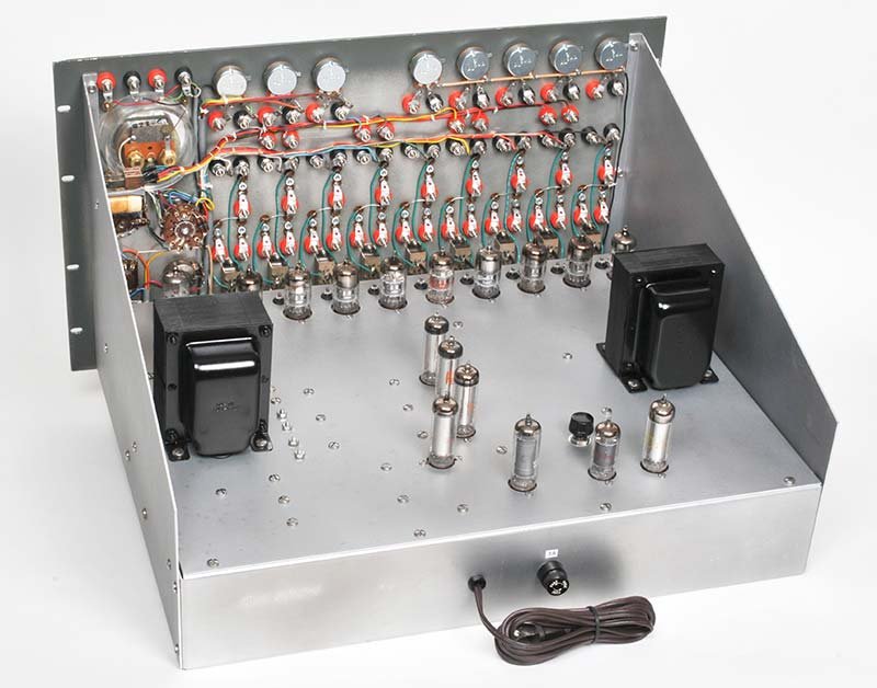
The restored chassis running with all nine 6U8 operational amplifiers installed. The five bus bars distributing +300 VDC, −150 VDC, and 6.3 VAC are visible as the horizontal rails spanning the chassis width. The purple glow of the OA2/OB2 VR tubes is characteristic of normal operation. Reproduced courtesy Nuts & Volts / David Goodsell (May 2016).
4.8 Troubleshooting Triage Table
The following table covers the most common post-restoration faults in approximate order of frequency. A systematic approach — power supply first, then individual amplifiers, then control circuits — reduces diagnostic time significantly.
Table 9 — Troubleshooting Triage Table
| Symptom | Most Likely Cause | Diagnostic Step | Remedy |
|---|---|---|---|
| Meter pegged full-scale at power-on | B+ out of regulation (>350 V) | Measure B+ bus with external meter; check VC trimmer | Adjust VC to +300 V; if unstable, replace main filter electrolytics |
| Meter dead, no deflection | B+ not present, or filaments off | Verify both FILAMENT and HIGH VOLTAGE switches on; check F1 fuse (2 A) | Replace fuse; trace open circuit |
| OA2 / OB2 VR tube does not glow | Tube defective, or B− supply open | Substitute known-good tube; measure −150 V rail | Replace VR tube; check rectifier diode continuity |
| All nine amplifiers cannot null (drift >5 V at 1 V range) | B+ rail at wrong voltage | Measure B+ with external meter | Readjust VC; check filter caps for excessive ripple |
| One amplifier cannot null despite new tube and fresh pot | 6U8 socket corrosion on pin 7 (pentode grid) | Clean socket pins with DeOxit; measure resistance from pin 7 to grid resistor | Replace socket if irreparable |
| Amplifier output oscillates at HF (audible hash) | HF filter cap (5600 pF) open or missing | Check 5600 pF ceramic cap between pentode plate and screen | Replace 5600 pF cap at that amplifier |
| 60 Hz hum in op-amp outputs during simulation | IC supply insufficiently isolated (Goodsell documented) | Identify hum source with scope; probe each IC supply output | Add small 120 VAC isolation transformer under chassis for V INI supply |
| No output from specific amplifier; meter reads zero even with input | 6U8 tube dead | Substitute known-good tube | Replace 6U8 in that socket |
| Relay does not cycle in REPETITIVE mode | 12BH7 multivibrator fault or timing cap open | Measure 12BH7 plate voltages; should alternate between ~150 V and ~20 V | Replace 12BH7; check timing capacitors (C16) |
| Relay cycles at wrong rate; REPETITION RATE pot has no effect | Timing pot (12BH7 cathode circuit) oxidized | Clean pot with DeOxit; check wiper continuity | Replace pot if DeOxit does not restore range |
| IC supply output does not vary with front-panel pot | OB2 VR tube not striking, or pot wiper open | Measure OB2 plate voltage; check wiper resistance to output | Replace OB2; clean or replace pot |
| Integration runaway — output reaches ±60 V instantly | Feedback capacitor leaky or shorted | Measure capacitor leakage at working voltage with a capacitor meter | Replace feedback cap (1 µF, 100 V) |
| Burn smell on power-up | Selenium rectifier overheating | Identify potted selenium stack by odor direction; measure forward drop | Replace with 1N4007 silicon diode (see note below) |
| Patch board socket broken / cracked | Physical damage | Inspect 27 two-pin crystal-type sockets for cracks | Source replacement at surplus-sales.com #EBY-HC6; or fabricate Delrin substitutes |
Selenium rectifier note. Some EC-1 units employed a mix of silicon and potted selenium rectifiers in the B+ rectifier chain. Selenium rectifiers have a forward drop of approximately 1 V per plate (stacks may total 5–10 V forward drop) and fail open or short with age, producing a characteristic acrid odor. Replace potted selenium units with 1N4007 silicon diodes (1.0 A, 1000 PRV); the lower forward drop (~0.7 V per diode vs. ~1 V per selenium plate) will slightly raise the B+ rail — verify by readjusting VC.
4.8.1 Patch-Cord Plug Fabrication
The original kit included 27 two-pin clear plastic plug assemblies used to mount simulation resistors and capacitors into the front-panel brown crystal sockets. These plugs are essentially unobtainable; the following approaches have been documented:
-
Delrin machining (Goodsell method): Mill rectangular blocks of Delrin or Nylon to the socket footprint (~0.4” × 0.9” × 0.4” tall). Drill two holes on the standard crystal socket pin pitch (0.200” centers). Press-fit octal tube pins (same diameter as the socket pins) into the holes; crimp component leads to the pins; pot with epoxy.
-
Banana jack leads: Insert component leads directly into the red/black binding post holes adjacent to each socket and tighten the knurled collar. Less elegant but immediately functional.
-
Surplus crystal holders: Some eBay sellers list FT-243 crystal holder bases — physically compatible with the EC-1 sockets. The two solder lug positions differ slightly; verify fit before ordering in quantity.
TWO-PIN PLUG — CROSS-SECTION (Goodsell fabrication)
──────────────────────────────────────────
   ┌──────────────────────────┐   ← Delrin block (approx. 0.4"×0.9")
   │  ●           ●           │   ← Octal tube pins, crimped to
   │  │           │           │     component leads
   │  [Component R or C body] │
   └──────────────────────────┘
         ↕ 0.200" pin pitch
──────────────────────────────────────────
Note — Socket Contact Fragility. The 27 brown crystal sockets on the front panel contain custom wiper contacts that are essentially irreplaceable. Handle with care; never force plugs sideways. The wiper contacts can be cleaned with silver contact cleaner applied with a toothpick.
4.9 Resistors, Potentiometers, and Ancillary Components
4.9.1 Carbon Resistors
Every carbon composition resistor in the EC-1 should be measured in-circuit (with power off) or out-of-circuit after desoldering. Carbon comp resistors drift upward with age; values 20–30% above nominal are common after 50 years. The Assembly Manual specifies 5% tolerance for most resistors.
Replacement recommendation: Substitute 1% metal-film resistors throughout. The improved stability (< ±0.01% per °C temperature coefficient for quality metal film vs. ±0.1% for carbon comp) directly reduces op-amp gain error and temperature drift. The physical dimensions of 1/2 W metal-film resistors are essentially identical to the original carbon comp parts.
Wire-wound power resistors (cathode resistors, screen resistors) are more stable and typically measure within 5% of original value even after decades. Test these but plan to retain them unless a fault is found.
4.9.2 Coefficient Potentiometers
Five 10-turn (or single-turn, depending on production run) coefficient potentiometers occupy the center of the front panel. These are the primary problem-programming controls and must operate smoothly across their full range.
- With tubes removed and power off, measure each pot end-to-end and from each end to wiper across the rotation range.
- A scratchy or dead zone anywhere in the rotation indicates oxide buildup: clean with DeOxit D5 aerosol, cycling the pot through full rotation 10–20 times.
- If cleaning does not restore smooth operation, replacement with a matching pot (value from schematic — typically 10 kΩ–25 kΩ single-turn wirewound) is preferred.
4.10 Power Supply SVG Diagram
The following SVG depicts the EC-1 power supply architecture schematically, showing the regulated supply topology:
4.11 Section Cross-References and Further Reading
- For complete DC op-amp circuit analysis (6U8 gain derivation, neon lamp level shift, positive feedback resistor function), see Vol 2 — Hardware & Theory of Operation.
- For the repetitive oscillator (12BH7 multivibrator, relay timing, 0.1–15 cps range) and patch panel, see Vol 2 and Vol 3 — Patch Panel & Computing Elements.
- For first-problem setup, scaling, and patch procedures using the restored machine, see Vol 5 — Programming.
- For the bouncing-ball simulation (all nine op-amps, 25 resistors, 5 capacitors, 2 diodes, 35 patch cords) including the documented 60 Hz hum fix, see Vol 6 — Sample Programs & Demonstrations.
4.12 Quick-Reference Cards
4.12.1 Tube Tester Minimum-Pass Values
Table 10 — Tube Tester Minimum-Pass Values
| Tube | Section | Minimum Gm (µmhos) | Reject If |
|---|---|---|---|
| 6U8 | Pentode | 2,500 | < 1,750 or gassy |
| 6U8 | Triode | 1,600 | < 1,100 |
| 12BH7 | Both triodes | 3,100 | < 2,200 or unbalanced >20% |
| 6AQ5 | — | 4,100 | < 2,900 or gassy |
| 6BH6 | — | 3,500 | < 2,450 |
| 0A2 | — | Strike / regulate at 150 V | Does not glow or regulate |
| 0B2 | — | Strike / regulate at 108 V | Does not glow or regulate |
4.12.2 Amplifier Balance Quick-Check (per amplifier)
Table 11 — Amplifier Balance Quick-Check (per amplifier)
| Step | Action | Pass Criterion |
|---|---|---|
| 1 | Press balance slide switch | Switch clicks, meter responds |
| 2 | Set METER RANGE to 100 V, adjust balance pot | Meter within ±5 V of zero |
| 3 | Set METER RANGE to 10 V, readjust | Meter within ±0.5 V of zero |
| 4 | Set METER RANGE to 1 V, readjust | Meter within ±0.05 V of zero |
| 5 | Release balance switch; apply +10 V input via 1 MΩ plug | Output reads −10 V ± 0.5 V |
4.12.3 Restoration Parts — Minimum Recommended Spares
Table 12 — Restoration Parts — Minimum Recommended Spares
| Item | Quantity | Estimated Cost |
|---|---|---|
| 6U8 tubes (tested) | 18 (2× complement) | $40–$90 (AES or VIVA) |
| 12BH7 | 2 | $8–$15 |
| 6AQ5 | 2 | $4–$8 |
| 0A2 | 2 | $6–$12 |
| 0B2 | 2 | $6–$12 |
| 1N4007 diodes (selenium replacements) | 10 | $2 |
| Electrolytic recap set (full) | 1 set | $60–$90 |
| 3 kΩ balance trimmer pots | 12 | $10–$20 |
| Rubber grommet assortment | 1 kit | $8–$15 |
| DeOxit D5 aerosol | 1 can | $15 |
| Red/black binding posts | 72 | $25–$45 |
| 16 AWG 3-conductor line cord | 1 | $8 |
End of Volume 4 — Acquisition & Restoration.
Comments (0)