Heathkit EC-1 · Volume 2
Heathkit EC-1 — Volume 2 — Hardware & theory of operation
Power supply architecture, 6U8-based op-amp topology, nine amplifier modules, metering and control circuitry, and stage-by-stage schematic walk — grounding all later volumes in measured hardware reality
2.1 About this Volume
This volume dissects the Heathkit EC-1 Educational Analog Computer at the circuit level, providing the depth of technical understanding required for confident restoration, calibration, and fault diagnosis. It covers every major subsystem from the mains transformer through the nine vacuum-tube operational amplifiers to the front-panel meter and control logic. The reader should be comfortable with vacuum-tube circuit theory, DC power supply design, and the feedback-amplifier analysis found in texts such as Korn and Korn, Electronic Analog Computers (McGraw-Hill, 1956).
Cross-references to other volumes in this series are as follows:
- Vol 1 — introduction, history, and acquisition guidance
- Vol 3 — patch panel, computing elements, and sign-convention
- Vol 4 — acquisition, restoration, alignment, and fault-finding procedures
- Vol 5 — programming methodology and problem scaling
- Vol 6 — sample programs and illustrative problems
All component designators cited in this volume follow the Heathkit Assembly Manual schematic numbering. Where the manual does not assign a designator, the part is described by location and function. Voltages are DC unless annotated “AC”.
Danger — The EC-1 operates with internal rails of approximately +300 V and −150 V with respect to chassis ground. These potentials are lethal. No work should be performed inside the chassis with power applied. The filter capacitors retain charge after power-down; wait at least 60 seconds and verify with an insulated meter probe before touching internal components. See Vol 4 for a safe power-down and discharge procedure.
2.2 System Block Diagram
The EC-1 can be understood as five functional blocks connected by a common signal ground and distributed power buses.
┌─────────────────────────────────────────────────────────────────────────────┐
│                          AC MAINS  105–125 V / 100 W                        │
└────────────────────────────┬────────────────────────────────────────────────┘
                             │
                    ┌────────▼────────┐
                    │  POWER SUPPLY   │
                    │                 │
                    │ +300 V @ 25 mA  │◄─── electronically regulated
                    │ −150 V @ 40 mA  │◄─── OA2 VR tube regulated (150 V)
                    │ +100 V (×3 IC)  │◄─── OB2 VR tube regulated (108 V), front-panel pots
                    │  6.3 VAC heater │◄─── transformer secondary, unregulated
                    └────────┬────────┘
                             │
           ┌─────────────────┼─────────────────────────────────────┐
           │   FIVE CHASSIS BUS BARS (run full chassis length)      │
           │  +300 V  │  −150 V  │  +IC  │  −IC  │  6.3 VAC heater │
           └──────────┼──────────┼───────┼───────┼─────────────────┘
                      │          │       │       │
          ┌───────────▼──────────▼───────▼───────▼──────────────────┐
          │         NINE IDENTICAL DC OP-AMP MODULES                 │
          │  Amp 1 ─ Amp 2 ─ Amp 3 ─ Amp 4 ─ Amp 5 ─ ...─ Amp 9   │
          │  Each: 6U8 triode/pentode, balance pot, socket strip      │
          └──────────────────────┬───────────────────────────────────┘
                                 │ ±60 V signal outputs
          ┌──────────────────────▼───────────────────────────────────┐
          │               FRONT-PANEL PATCH SYSTEM                   │
          │  27 × two-pin sockets (R/C plug-ins)                     │
          │  9 × amplifier output binding posts (RED)                │
          │  9 × amplifier summing-junction posts (BLACK)            │
          │  5 × coefficient potentiometers                          │
          │  3 × initial-condition (IC) power supply binding posts   │
          │  4 × relay contact binding posts                         │
          └──────────────────────┬───────────────────────────────────┘
                                 │
          ┌──────────────────────▼───────────────────────────────────┐
          │          METERING & CONTROL CIRCUITRY                    │
          │  50-0-50 µA meter movement                               │
          │  METER FUNCTION switch (Amp select / IC monitors)        │
          │  METER RANGE switch (×1 / ×10)                           │
          │  OPERATION switch (RESET / OPERATE / REPETITIVE)         │
          │  12BH7 multivibrator repetitive oscillator (0.1–15 cps)  │
          │  6AQ5 relay driver + 4× relay contacts                   │
          │  Oscilloscope output jacks                               │
          └──────────────────────────────────────────────────────────┘
The signal ground is the aluminum front panel and chassis, tied to one side of the transformer secondary. No floating grounds exist in the EC-1 design. The ±60 V computing signal range occupies the low-impedance output of each op-amp and is referenced entirely to this single chassis ground, which eliminates common-mode interference between amplifiers.
2.3 Power Supply — +300 V and −150 V Rails, Heater String, Turn-On Sequencing
2.3.1 Transformer and Rectifiers
The mains transformer provides several secondaries:
Table 1 — The mains transformer provides several secondaries
| Secondary | Nominal Voltage | Load | Purpose |
|---|---|---|---|
| HV winding 1 | ~350 V AC | Rectifier B+ string | +300 V regulated supply |
| HV winding 2 | ~200 V AC | Rectifier bias string | −150 V regulated supply |
| IC winding | ~120 V AC (×3) | Three separate rectifiers | Initial-condition ±100 V supplies |
| Heater | 6.3 V AC | All 9× 6U8 heater pairs + other tubes | Filament heating |
Danger — Both HV secondaries carry voltages capable of delivering a fatal shock. The transformer secondary voltages rise to full value within one AC half-cycle of power application. Capacitors on these rails charge to peak voltage (~495 V peak on the B+ winding) before regulation clamps the rail. The chassis provides no inherent interlock; power must be physically disconnected before opening the cabinet.
Early production EC-1 units used selenium rectifier stacks (potted multi-plate assemblies) for the HV rectification. Selenium rectifiers have a characteristic failure mode in which the stack develops high forward resistance and emits a pungent burned odor; they present a possible fire hazard. Any unit still using selenium devices should have them replaced with 1N4007 silicon diodes (400 V PIV, 1 A) before restoration. The physical selenium package may be retained for cosmetic purposes if desired.
Later production units used silicon diodes from the factory.
2.3.2 +300 V Electronically Regulated Supply
The +300 V supply is the primary computing rail. The Heathkit circuit uses a conventional electronic voltage regulator — a series-pass vacuum-tube stage controlled by an error amplifier (6BH6) that compares a divided sample of the output against a fixed reference. The OA2 and OB2 VR tubes serve their respective separate supply rails (−150 V and IC supplies); they are not part of the +300 V regulation path.
HV Secondary
     │
  [Full-wave
   rectifier]──[C_filter]──┬──[R_series]──[V_pass tube plate]──► +300 V out
                           │                     │
                           │              [V_pass tube grid]
                           │                     │
                           └──[6BH6 error amp]───┘
                                  │
                                 GND
The 6BH6 driver stage provides the error-amplifier function for the electronic regulator, comparing a divided sample of the output against a reference to control the series-pass tube. The regulated output is adjustable and the circuit provides clean, low-ripple regulation.
The pass tube grid is controlled by the error amplifier; any tendency for the output to rise causes the pass tube to conduct less, reducing the output — classic series-pass regulation.
The regulated output is adjustable from approximately +250 V to +350 V via a front-panel pot labeled HIGH VOLTAGE. The design center for analog computation is +300 V, at which point the amplifier gain and the ±60 V output swing are correctly scaled. Deviating from +300 V changes the effective gain of each op-amp and shifts the usable output range.
Supply specifications:
Table 2 — Supply specifications:
| Parameter | Value |
|---|---|
| Nominal output | +300 V DC |
| Adjustment range | +250 to +350 V |
| Maximum continuous load | 25 mA |
| Ripple at full load (typical) | < 5 mV rms |
| Regulation tube | Series-pass triode (6BH6 as driver stage) |
| Reference elements | 6BH6 error amplifier + series-pass regulator |
| Filter capacitor(s) | Electrolytic, original spec 40 µF / 450 V |
2.3.3 −150 V OA2 Regulated Supply
The negative supply provides the cathode bias and one plate supply rail for the op-amp stages. It is regulated by a single OA2 VR tube operating in its glow-discharge region; the OA2 regulates at 150 V. The −150 V rail draws up to 40 mA at full complement of nine amplifiers operating.
The distinctive purple-blue corona glow visible through the ventilation slots of a running EC-1 comes from these VR tubes. The hue is a spectroscopic signature of neon (OA2) or argon (OB2) fill gas excited by the regulation discharge current — typically 5–15 mA per tube.
2.3.4 Initial-Condition (IC) Supplies
Three separate IC supplies each derive from an isolated transformer secondary; each is regulated by an OB2 VR tube (108 V regulation). Each IC supply produces approximately ±100 V. The front panel provides binding posts for each IC supply at the +IC and −IC jacks adjacent to each supply’s panel pot. The operator sets the desired initial condition voltage (0 to ±60 V at the patch point) using the panel potentiometer; the op-amp input network referenced to the IC rail charges the integrating capacitor to this voltage during the RESET phase.
The IC supplies are not regulated because absolute accuracy is unnecessary — only repeatability matters, and the main op-amp feedback loop tracks out small IC supply variations during OPERATE mode.
2.3.5 Heater Supply and Warm-Up Sequencing
The 6.3 V AC heater winding energizes all tube heaters simultaneously with AC power application. The EC-1 has no warm-up delay interlock; the HV rail rises immediately while the cathodes are still cold. This is not ideal tube practice but was acceptable for the EC-1’s intended service life and cost target. The operator is instructed to allow a few minutes of warm-up before running problems.
During a restoration, it is best practice to verify that the heater winding delivers 6.0–6.6 V AC under load (heaters are series-parallel wired). An out-of-tolerance heater supply indicates a shorted heater or marginal transformer.
Heater current draw estimate (all tubes operating):
Table 3 — Heater current draw estimate (all tubes operating):
| Tube | Qty | Heater V | Heater mA each | Total mA |
|---|---|---|---|---|
| 6U8 | 9 | 6.3 V | 450 mA | 4,050 mA |
| 12BH7 | 1 | 6.3 V | 600 mA | 600 mA |
| 6AQ5 | 1 | 6.3 V | 450 mA | 450 mA |
| 6BH6 | 1 | 6.3 V | 300 mA | 300 mA |
| OA2 | 1 | 6.3 V | 300 mA | 300 mA |
| OB2 | 1 | 6.3 V | 300 mA | 300 mA |
| Total | 14 | — | — | ~6.0 A |
The 6.3 V winding must be rated for at least 7 A; the Heathkit transformer is wound to this margin.
2.4 The Vacuum-Tube DC Operational Amplifier — Topology, Gain, Drift, Balance
2.4.1 Topology Overview
The EC-1 operational amplifier is a two-stage, direct-coupled, inverting DC amplifier using a single 6U8 envelope. The 6U8 is a compactron-era miniature tube containing one triode section and one pentode section in the same glass envelope. Heathkit exploits both sections in a single gain chain.
                      +300 V
                         │
                    [Pentode Plate Load]
                         │
INPUT ──[Ri]──►[SJ]──►[Pentode Grid]──►[Pentode]──►[Triode Grid]──►[Triode]──► OUTPUT
               │                                                         │
               └─────────────────[Rf or Cf feedback]────────────────────┘
                                                                         │
                                                                       −150 V
(cathode bias)-
First stage (pentode): The pentode section provides the bulk of the open-loop voltage gain — typically 150–300× at the operating point. The pentode grid is the summing junction (SJ), the virtual-ground node of the amplifier. High pentode transconductance (gm ≈ 5 mA/V for the 6U8A) gives low output impedance from this stage.
-
Second stage (triode): The triode section acts as a common-cathode voltage amplifier and phase inverter, adding an additional gain stage and providing sufficient output current drive to swing ±60 V into the patch-panel impedances. The triode plate serves as the amplifier output.
-
Overall open-loop gain (A): Approximately 1,000 at DC, falling at higher frequencies. The −1 dB bandwidth is 600 Hz, limiting the machine to low-frequency simulation work.
The summing junction is held at virtual ground by the deep negative feedback. For any practical computation, the summing junction sits within a few millivolts of chassis ground potential. This is a critical property: it allows multiple input resistors to be paralleled at the junction without interaction between sources.
2.4.2 Gain and Error Analysis
With open-loop gain A ≈ 1,000, the closed-loop gain error relative to the ideal (infinite-A) case is:
Closed-loop gain (actual) = (Rf/Ri) × [A/(A+1+Rf/Ri)]For typical values Rf = 1 MΩ and Ri = 1 MΩ (unity inversion), with A = 1,000:
Actual gain ≈ 0.999 × ideal gain → 0.1% gain errorFor Rf/Ri = 10 (scaling by 10), the error rises to approximately 1%. This is consistent with the ±1% resistor tolerance of problem-element resistors and is the dominant accuracy limit of the machine rather than the amplifier itself.
Note — The EC-1 Operational Manual (p. 7) confirms that ratios Rf/Ri greater than 100 introduce unacceptable inaccuracies because the denominator term [A/(A + 1 + Rf/Ri)] departs significantly from unity. Problem setups should be scaled to keep all resistor ratios at 10:1 or less.
2.4.3 DC Drift and Balance
DC operational amplifiers are plagued by input offset voltage — any asymmetry in the input stage appears as an error voltage at the summing junction, indistinguishable from a real input. Sources of offset in the 6U8 amplifier include:
Table 4 — DC operational amplifiers are plagued by input offset voltage — any asymmetry in the input stage appears as an error voltage at the summing junction, indistinguishable from a real input. Sources of offset in the 6U8 amplifier include
| Source | Typical Magnitude | Notes |
|---|---|---|
| Pentode grid-cathode contact potential | 0.5–2 V equivalent | Varies with tube age and cathode chemistry |
| Power supply noise coupling | Depends on bypassing | More significant on +300 V than −150 V |
| Heater–cathode leakage | Increases with age | Primary failure mode in old 6U8s |
| Resistor mismatch in plate loads | < 0.1 V typical | Stable once resistors are in-tolerance |
| Thermal EMF at solder joints | < 1 mV | Usually negligible |
The amplifier balance pot (3 kΩ, one per amplifier, mounted along the bottom of the front panel) corrects for input offset. It applies a small differential voltage to the pentode control grid through a resistive bridge. Proper balance procedure:
- Short the summing junction to ground (no input connections).
- Switch METER FUNCTION to the amplifier’s output.
- Adjust the balance pot until the meter reads exactly zero.
- Restore connections and run the problem.
The balance adjustment must be repeated after tube substitution, after extended warm-up, or whenever the ambient temperature changes significantly. Carbon-composition balance pots are susceptible to wiper contamination and should be replaced with wire-wound or cermet types during restoration.
2.4.4 Frequency Response
The EC-1 specifies −1 dB at 600 Hz. The roll-off arises primarily from:
- Stray capacitance at the summing junction — the physical node at the patch panel accumulates capacitance from nine parallel amplifier input sockets, banana binding posts, and patch-cord distributed capacitance. Total stray at the SJ is estimated at 50–200 pF.
- Miller effect on the pentode plate:** The plate-grid capacitance (Cgp ≈ 0.01 pF for the 6U8 pentode, very low by design) contributes less than the external strays.
- Output stage bandwidth — the triode section introduces an additional pole at several kHz.
For practical purposes, the EC-1 is suitable for simulations requiring time constants from approximately 1 ms (1 µF × 1 kΩ) to thousands of seconds. The 600 Hz bandwidth is not a limitation for mechanical, thermal, or biological differential equation problems, which constitute nearly all educational use cases.
2.5 The Nine Amplifiers — Identical Modules, How Configured
2.5.1 Physical Arrangement
The nine amplifier modules are arranged in a single row across the top of the front panel. Each module occupies an identical vertical slice of the front panel and chassis, giving the EC-1 its distinctive appearance.
Each module consists of:
- One 9-pin miniature tube socket (for the 6U8) mounted on the chassis floor
- Two binding post pairs on the front panel (one red OUTPUT, one black AMPLIFIER INPUT)
- One or two two-pin patch sockets immediately adjacent to the binding posts for problem-element plug-ins
- One balance potentiometer along the bottom row of the front panel
- Wiring harness connecting socket pins to binding posts and bus bars
2.5.2 Electrical Configuration per Module
Every module is wired identically. The front panel connections seen by the operator are:
Table 5 — Every module is wired identically. The front panel connections seen by the operator are
| Front Panel Element | Internal Node | Function |
|---|---|---|
| AMPLIFIER INPUT (black) | Summing junction (pentode grid via Ri_internal) | Signal input(s) arrive via problem-element resistors patched here |
| AMPLIFIER OUTPUT (red) | Triode plate | ±60 V output; drives problem-element feedback Rf/Cf and next stage inputs |
| Two-pin socket (left) | Paralleled across INPUT and OUTPUT | Accepts resistor or capacitor plug for feedback element Rf or Cf |
| Two-pin socket (right) | Same paralleled topology | Second plug position for dual-element feedback configurations |
| Balance pot | Pentode grid bias bridge | Nulls DC offset |
The same physical socket pair that accepts a 1 MΩ feedback resistor (for inverter/summer operation) also accepts a 1 µF capacitor (for integrator operation). This is the fundamental versatility of the analog computer: the function of each amplifier is determined entirely by the passive elements plugged in — not by any internal switching.
2.5.3 Amplifier Function Configuration Table
Table 6 — 5.3 Amplifier Function Configuration Table
| Plug-in elements | Feedback element | Result |
|---|---|---|
| Ri = 1 MΩ (input socket) | Rf = 1 MΩ (feedback socket) | Inverter, gain = −1 |
| Ri = 1 MΩ (input socket) | Rf = 10 MΩ (feedback socket) | Inverting amplifier, gain = −10 |
| Ri₁, Ri₂, Ri₃ (multiple inputs) | Rf = 1 MΩ | Weighted summer: eo = −(Rf/Ri₁·e₁ + Rf/Ri₂·e₂ + …) |
| Ri = 1 MΩ (input socket) | Cf = 1 µF (feedback socket) | Integrator: eo = −(1/RC)∫ei dt = −(1 s⁻¹)∫ei dt |
| Ri = 100 kΩ (input socket) | Cf = 1 µF | Integrator with τ = 0.1 s |
| Ci (input socket) | Rf = 1 MΩ | Differentiator (noise-amplifying; avoid in practice) |
| Coefficient pot + Ri | Rf | Scaler with variable coefficient 0–1 |
Note — Heathkit specifies 1 MΩ as the standard resistor value for problem elements and 1 µF for standard capacitors. These values set the integration time constant RC = 1 second, convenient for human observation. Non-standard values are used for time scaling and for coefficient adjustment. Vol 3 covers problem scaling in detail.
2.5.4 Amplifier Module Tube Data
The 6U8 (also marketed as ECF82 in European nomenclature) is a medium-mu triode / sharp-cutoff pentode in a 9-pin miniature (Noval) envelope.
Table 7 — 5.4 Amplifier Module Tube Data
| Parameter | Triode Section | Pentode Section |
|---|---|---|
| Heater | 6.3 V, 450 mA | (shared envelope) |
| Max plate voltage | 300 V | 300 V |
| Typical plate voltage (EC-1) | ~150 V | ~250 V |
| Max grid voltage | — | −55 V (G1) |
| Transconductance (gm) | 3.1 mA/V | 5.0 mA/V |
| Amplification factor (µ) | 19 | — |
| Plate resistance (rp) | 6.1 kΩ | 300 kΩ (pentode) |
| Max dissipation | 1.8 W (plate) | 3.3 W (plate) |
| Socket | 9-pin miniature | (same envelope) |
The 6U8 was widely manufactured by RCA, Sylvania, GE, Mullard, and Philips. All brands are electrically interchangeable in the EC-1. NOS (new old stock) and used-tested specimens are readily available from Antique Electronic Supply, VIVA Tubes, and similar vendors (see Vol 4 for sourcing guidance).
2.6 Metering and Mode/Control Circuitry
2.6.1 Meter Movement
The EC-1 uses a 50-0-50 µA D’Arsonval meter movement with a center-zero scale. The meter is protected by series resistors that scale the deflection to the EC-1’s ±60 V output range.
With the METER RANGE switch at ×1:
- Full-scale deflection (50 µA) corresponds to ±50 V at the selected amplifier output.
- Sensitivity: approximately 1 µA / V → 1 division per volt on a 50-division scale.
With METER RANGE at ×10:
- Scale is multiplied; full deflection corresponds to ±5 V, providing 10× sensitivity for balance adjustment and low-level signal monitoring.
2.6.2 METER FUNCTION Switch
A multi-position rotary switch routes the desired signal to the meter. Positions include:
Table 8 — A multi-position rotary switch routes the desired signal to the meter. Positions include
| Switch Position | Signal Monitored |
|---|---|
| AMP 1 – AMP 9 | Output of the selected operational amplifier |
| IC-1, IC-2, IC-3 | Voltage at each initial-condition power supply output (set by panel pot) |
| OFF | Meter disconnected |
The AMPLIFIER OUTPUT terminals used for metering are the same nodes connected to the amplifier output binding posts — reading the meter does not load the amplifier separately.
2.6.3 OPERATION Mode Switch
The three-position OPERATION switch governs the computation cycle:
Table 9 — The three-position OPERATION switch governs the computation cycle
| Position | Action | Internal state |
|---|---|---|
| RESET | All relay contacts closed; integrating capacitors discharged to IC voltages | Relay driver energized; amplifiers are hold mode |
| OPERATE | Relay contacts open; computation begins | Relay driver de-energized; normal amplifier operation |
| REPETITIVE | Multivibrator drives relay at set rate | Relay cycles between RESET and OPERATE automatically |
Note — During RESET, the relay contacts connect each integrator’s feedback capacitor directly to the relevant IC supply voltage through a 100 kΩ series resistor. The capacitor charges to the IC voltage within a few time constants (typically < 100 ms). Switching to OPERATE releases the capacitor; integration proceeds from the preset initial condition.
2.6.4 Relay and Relay Driver
The EC-1 uses a single relay with four sets of contacts (4PST). The relay coil is energized by the 6AQ5 pentode, which receives its gate signal from the OPERATION switch.
The four contact sets are:
- Shorting contacts across each integrating feedback capacitor (for RESET)
- Contacts that connect the IC supply voltages to the integrator input networks (for RESET)
- Output-disconnect contacts isolating the oscilloscope output during RESET transient
- A spare contact set available to the operator via front-panel RELAY CONTACTS binding posts (usable as a logic input for nonlinear simulations such as the bouncing-ball problem)
The 6AQ5 is rated at 4.5 W plate dissipation and can comfortably drive the relay coil current (typically 50–100 mA at 12–24 V DC for the Heathkit relay used).
2.6.5 Repetitive Oscillator (12BH7 Multivibrator)
The repetitive-operation oscillator is an astable multivibrator built around the 12BH7 dual triode. The two triode sections cross-couple through RC networks to produce a square-wave output that alternately triggers the relay driver between RESET and OPERATE states.
Oscillator timing:
Table 10 — Oscillator timing:
| Control | Effect |
|---|---|
| REPETITION RATE pot (front panel) | Adjusts RC time constant; range 0.1 to 15 Hz (0.1 to 15 cps per original specification) |
| REPETITION RATE at minimum | ~67 ms per half-cycle (15 Hz) — useful for oscilloscope display |
| REPETITION RATE at maximum | ~10 s per half-cycle (0.1 Hz) — slow visual observation |
At repetitive rates of 5–15 Hz, the output waveform repeats fast enough to produce a stable trace on a DC-coupled oscilloscope in X-Y mode, allowing continuous real-time observation of the solution.
The 12BH7 is a robust tube with good service life; failures are uncommon. When the multivibrator does fail, the symptom is loss of repetitive operation with normal single-OPERATE function intact. Replacement is straightforward (see Vol 4).
2.6.6 Oscilloscope Output Jacks
Two binding posts labeled SCOPE OUTPUT X and SCOPE OUTPUT Y (or equivalent labeling depending on production date) provide buffered access to the amplifier outputs for external oscilloscope connection. These jacks are protected by series resistors (typically 1 kΩ) to prevent oscilloscope input damage if the operator connects a scope probe to a high-impedance source.
The EC-1 Operational Manual specifically recommends the Heathkit IO-10 (3-inch CRT scope), OR-1, or OP-1 oscilloscopes as period-correct accessories. Any DC-coupled oscilloscope set to the 20 V/div or 50 V/div range is electrically compatible.
Danger — The EC-1 amplifier outputs reach ±60 V under normal operating conditions. Connecting an oscilloscope with input sensitivity settings below 5 V/div risks overdriving the oscilloscope input stage and may cause damage. Always begin with 20 V/div or greater and reduce sensitivity only after confirming signal amplitude.
2.7 Schematic Walk by Stage with Component Callouts
2.7.1 Reading the Schematic
The full schematic (Heathkit EC1 Schematic.pdf, one sheet) is dense but logically partitioned. From left to right it presents: AC input, transformer, rectifiers, regulator pass tube, VR tube stack, IC supplies, the nine amplifier sub-circuits (drawn identically for Amps 1–9 as a collapsed array), then the meter, relay, and multivibrator circuits.
2.7.2 AC Input Stage
Fuse F1 (3 A, slow-blow) protects the primary. Capacitor C_line (0.01–0.05 µF, rated 600 V) across the mains provides RF bypass and reduces radio-frequency emissions. The power switch (front panel) interrupts the primary; both legs are switched together.
The transformer primary is tapped for 105–125 V, with the tap chosen at assembly to match the local supply. Most US units are set to the 117 V tap.
2.7.3 High-Voltage Rectifier and Filter Stage
The HV secondary feeds a full-wave rectifier (two rectifier diodes, original selenium or replacement silicon). The rectified DC appears across the main filter capacitor bank. Original specification is 40 µF at 450 V working.
Danger — The filter capacitors on the +300 V rail charge to peak rectified voltage (~490 V peak from a 350 V AC secondary) before the regulator clamps the rail. Even with mains disconnected, these capacitors retain charge sufficient for a lethal shock. Electrolytic capacitors that have not been reformed for years should be treated as potentially explosive as well as electrically hazardous. Follow the slow-reform procedure in Vol 4 before applying full mains voltage to an unrestored unit.
After the main filter, the voltage passes through the series-pass regulator tube (triode connection, driven by a 6BH6 driver stage). The regulated output is metered by a string of dropping resistors to the front-panel HIGH VOLTAGE control pot, which sets the regulation point. The feedback error amplifier (6BH6) compares the pot wiper voltage with a reference and adjusts the pass tube grid bias accordingly.
2.7.4 Negative Supply (−150 V) Regulator Stage
The negative supply rectifier feeds a simpler regulation circuit. A single OA2 VR tube is connected between the raw negative rail and ground; it strikes at its characteristic breakdown voltage and regulates at 150 V, clamping the negative rail to −150 V through a dropping resistor network.
The filter capacitor on the −150 V rail is typically 50–100 µF at 200 V (note: this is a negative rail, so the capacitor’s positive terminal is at ground, negative terminal is at −150 V).
2.7.5 One Amplifier Module (Representative — all nine identical)
The 6U8 tube socket wiring in one amplifier module follows this signal path:
Pin 9 (Pentode G1 = control grid) ── summing junction ── input socket(s), balance bridge
Pin 5 (Pentode plate) ─────────────── plate load R (~100 kΩ) ── to +300 V
Pin 7 (Pentode G2 = screen) ──────── screen dropping resistor ── to +300 V (~150 V at G2)
Pin 6 (Pentode G3/suppressor) ────── internal to cathode
Pin 8 (Pentode cathode) ─────────── cathode resistor ── to −150 V

Pin 2 (Triode grid) ─────────────── pentode plate (direct-coupled)
Pin 1 (Triode plate) ─────────────── plate load R ── to +300 V → AMPLIFIER OUTPUT binding post
Pin 3 (Triode cathode) ───────────── cathode resistor ── to −150 V

Heater: Pins 4 & 5 (shared with pentode envelope at Pin 5) ── 6.3 V AC bus bars
The balance pot (3 kΩ) sits between a positive reference tap and ground, with the wiper feeding a small DC correction voltage to the pentode control grid through a high-value series resistor (~1 MΩ). The correction range is ±several volts at the wiper, attenuated to ±tens of millivolts at the grid after the 1:100 resistor divider — sufficient to null the typical tube offset.
Plate load resistors are 1% metal-film types (original Heathkit used carbon-film with a 5% tolerance; upgrading to 1% metal film significantly improves channel-to-channel tracking). Typical values are 100–220 kΩ for the pentode plate and 47–100 kΩ for the triode plate.
Screen decoupling is provided by an individual bypass capacitor on each module’s screen supply rail. Loss of this capacitor causes instability and high-frequency oscillation in the affected module.
2.7.6 Front Panel and Patch Board Wiring
From the tube socket, wire runs to a strip of 3-lug terminal strips along the chassis floor below the front panel. From there, individual wires connect to:
- The red OUTPUT binding post (triode plate)
- The black INPUT binding post (summing junction / pentode G1)
- The two-pin plug sockets immediately adjacent to each amplifier’s binding posts
The two-pin plug sockets are wired in parallel between the INPUT and OUTPUT posts. This means a resistor plugged into either socket appears directly between summing junction and amplifier output — i.e., as the feedback element Rf. Additional resistors at the INPUT post proper (banana jacks) appear as input resistors Ri. This topology allows the operator to combine input elements (from binding posts) with feedback elements (from plug sockets) in any combination.
2.7.7 Meter, Relay, and Multivibrator Stage
The METER FUNCTION wafer switch (12-position) feeds the selected amplifier output (or IC voltage) through a precision attenuator to the 50-0-50 µA movement. Two resistor values corresponding to the ×1 and ×10 RANGE positions complete the attenuator.
The 6AQ5 relay driver has its grid tied to the OPERATION switch. When the switch is at OPERATE, the 6AQ5 grid is biased to cut-off; the relay is de-energized and contacts are in the compute position. At RESET, the 6AQ5 conducts through the relay coil; the coil current pulls the relay armature and connects all RESET paths.
The 12BH7 multivibrator consists of the two triode sections cross-coupled:
- Triode A plate load resistor (~100 kΩ) coupling through a timing capacitor (~0.1–1 µF, sets the cycle period) to Triode B grid.
- Triode B plate load coupling through its timing capacitor to Triode A grid.
- The REPETITION RATE front-panel pot adjusts the timing capacitor’s charging resistor in series, varying frequency from 0.1 to 15 Hz.
When the OPERATION switch is at REPETITIVE, the multivibrator output is connected to the 6AQ5 relay driver grid, overriding the direct OPERATE/RESET control.
2.7.8 Initial Condition Supply Detail
Each of the three IC supplies uses an isolated transformer secondary feeding a full-wave rectifier and a simple RC filter. The rectified voltage is approximately ±100 V (relative to IC supply ground, which is also chassis ground). The front-panel IC pot (linear taper, 10 kΩ) forms a voltage divider across the ±100 V span; the wiper provides the desired IC voltage at the binding post. A series resistor (100 kΩ) prevents excessive current if the IC binding post is accidentally shorted to another potential.
Key IC supply specifications:
Table 11 — Key IC supply specifications:
| Parameter | Value |
|---|---|
| Unloaded output voltage | ±100 V |
| Pot range | 0 to ±60 V at wiper (full travel) |
| Series protection resistor | 100 kΩ |
| Filter capacitor | 10–25 µF / 150 V |
| Ripple at full IC load | < 1 V (acceptable; IC is set during RESET, not compute) |
2.7.9 Power Bus Distribution
Five bus bars run the full length of the chassis from left (power supply board) to right (amplifier 9). Each bus bar is a tinned-copper wire or strip clamped to insulating standoffs. The five buses are:
Table 12 — Five bus bars run the full length of the chassis from left (power supply board) to right (amplifier 9). Each bus bar is a tinned-copper wire or strip clamped to insulating standoffs. The five buses are
| Bus | Voltage | Connected to |
|---|---|---|
| B+ | +300 V | Pentode and triode plate loads, screen dropping resistors |
| B− | −150 V | Pentode and triode cathode resistors |
| IC+ | +IC (variable) | IC supply positive rail |
| IC− | −IC (variable) | IC supply negative rail |
| H | 6.3 V AC | All heater pins |
The five-bus architecture is responsible for the EC-1’s relatively clean inter-channel rejection. All nine amplifiers share the same regulated rails with local bypass capacitors on each module. In the original design, bypass capacitors are 0.01 µF ceramic types across each power pin to ground; these degrade with age but rarely fail completely.
2.8 Known Failure Points, Ageing Patterns, and Forward Reference to Vol 4
2.8.1 Electrolytic Capacitor Failure
Probability: High. Consequence: Severe.
Electrolytic capacitors manufactured in the 1960s use an aluminium-oxide dielectric formed on the anode foil by electrolytic oxidation. After 50+ years of storage, the oxide layer partially dissolves back into the electrolyte, and the capacitors exhibit dramatically reduced capacitance, elevated ESR, and high leakage current.
The failure spectrum in the EC-1:
Table 13 — The failure spectrum in the EC-1
| Location | Failure Mode | Symptom |
|---|---|---|
| Main HV filter cap (+300 V rail) | Low C, high ESR, leakage | Excessive ripple, low +300 V under load, possible catastrophic failure |
| Negative supply filter cap | Low C, high leakage | Oscillation, instability, −150 V sag |
| IC supply filter caps | Low C | IC voltage error during RESET |
| Screen bypass caps (per amplifier) | Open or short | Instability in one or all amplifiers |
| Multivibrator timing caps | Value drift | Repetition rate error |
| Coupling caps (if any) | Open | Loss of stage |
Danger — A shorted or leaky main filter capacitor on the +300 V rail can produce sustained fault currents through the power supply wiring. In a worst case, the series-pass regulator tube fails short, applying full raw-rectified voltage (~490 V peak) to the +300 V bus and potentially destroying all nine 6U8 amplifier tubes simultaneously. Always verify capacitor health before first power-up of an unrestored unit. See Vol 4 for the variac reform procedure.
Recommended action at restoration: Replace all electrolytic capacitors with modern types of equal or higher voltage rating. Use the original capacitor sleeves (slit open, remove old can, slide new cap inside) to preserve cosmetic appearance if desired. AES (tubesandmore.com) and Digi-Key are the primary sources.
2.8.2 Balance Potentiometer Degradation
Probability: Very High. Consequence: Moderate.
The nine front-panel balance potentiometers are 3 kΩ wire-wound or carbon-track types. After decades, the wiper tracks develop oxide layers and intermittent contact. The symptom is an inability to null one or more amplifiers — the meter refuses to go to zero despite pot adjustment, or the null point shifts with mechanical vibration.
Replacement with 3 kΩ cermet or wire-wound pots (knob-shaft style for convenience) is standard practice. See Vol 4.
2.8.3 6U8 Tube Ageing
Probability: Moderate. Consequence: Moderate.
The 6U8 is a relatively robust tube. Primary failure modes:
Table 14 — The 6U8 is a relatively robust tube. Primary failure modes
| Mode | Detection | Notes |
|---|---|---|
| Cathode depletion | Low emission on tube tester | Gradual onset; amplifier gain falls, offset worsens |
| Heater–cathode leakage | Hum on amplifier output | 60 Hz modulation of output; more common in aged tubes |
| Gassy tube | Erratic behavior, blue glow in envelope | Gas ions cause positive grid current; amplifier oscillates |
| Open heater | Cold tube, no output | Usually immediately obvious |
The EC-1 uses 9 × 6U8, plus one each of 12BH7, 6AQ5, OA2, OB2, 6BH6 — all of which are readily available as NOS or pull-tested. A full tube replacement set costs $40–$80 at time of writing.
2.8.4 Selenium Rectifier Replacement
Probability: Present in pre-~1965 units. Consequence: High if unreplaced.
Selenium rectifiers present two hazards: electrical (high forward drop and elevated leakage causing incorrect supply voltages) and chemical (burning selenium produces toxic selenium dioxide fumes). All selenium rectifiers must be replaced with 1N4007 silicon diodes during restoration regardless of apparent condition.
2.8.5 Carbon Resistor Drift
Probability: Moderate (up to 30% drift in some resistors). Consequence: Low to Moderate.
Carbon-composition resistors of 1960s manufacture are notorious for drifting high with age. In the EC-1 signal path, this most affects:
- Pentode plate load resistors (shifts op-amp operating point, degrades gain)
- Balance bridge resistors (shifts null range)
- IC supply series resistors (minor effect, but shifts IC accuracy)
Test all resistors in situ (power off, one lead lifted) against the schematic value. Replace any resistor measuring more than ±5% of nominal. 1% metal-film replacements are preferred.
2.8.6 Patch-Board Binding Post Corrosion
Probability: Very High. Consequence: Low (connection quality).
All front-panel banana binding posts tarnish and develop oxidized contact surfaces. The symptom is intermittent connections and high contact resistance (measurable as noise on amplifier outputs when flexing a patch cord). A complete set of replacement red and black banana binding posts (approximately 60–80 posts total) costs under $30 and dramatically improves reliability and appearance.
2.8.7 Two-Pin Plug Socket Integrity
Probability: Low. Consequence: Moderate if failed.
The 27 brown two-pin sockets for problem-element plug-ins are phenolic wafer sockets with brass-spring contacts. These rarely fail but can lose spring tension if repeatedly forced with oversized plug stems. Replacement sockets are not available as direct replacements; machined reproductions from Delrin rod stock are the only option (see Vol 4).
2.8.8 Known Failure Table: Triage Summary
Table 15 — 8.8 Known Failure Table: Triage Summary
| Symptom | Most Likely Cause | Second Possibility | See |
|---|---|---|---|
| All amplifiers unstable/oscillating | +300 V excessive (regulator failure) | Shorted screen bypass cap (multiple) | Vol 4 §4.3 |
| One amplifier cannot be balanced | Weak/gassy 6U8 | Bad balance pot | Vol 4 §4.4 |
| One amplifier no output | Dead 6U8 (open plate or heater) | Wiring break at binding post | Vol 4 §4.4 |
| 60 Hz hum on all outputs | Heater–cathode leakage (multiple 6U8) | IC supply coupling into amps | Vol 4 §4.5 |
| Relay does not cycle in REPETITIVE | Bad 12BH7 | Dried timing capacitor | Vol 4 §4.6 |
| Relay stays in RESET | 6AQ5 plate-to-cathode short | Relay coil winding open | Vol 4 §4.7 |
| OA2/OB2 does not glow | VR tube gone | Dropping resistor open | Vol 4 §4.3 |
| +300 V reads −200 or erratic | HV filter cap shorted/leaky | Rectifier reverse-leakage | Vol 4 §4.2 |
| IC voltage wrong by fixed offset | IC pot dirty | IC filter cap leaky | Vol 4 §4.8 |
| Meter pegged on all positions | +300 V on meter circuit | Meter shunt resistor open | Vol 4 §4.9 |
2.9 Reference Tables and Component Data
2.9.1 Complete Tube Complement
Table 16 — Complete Tube Complement
| Tube | Qty | Location | Function | Heater | Availability |
|---|---|---|---|---|---|
| 6U8 (ECF82) | 9 | Amplifier 1–9 sockets | DC operational amplifier (triode + pentode) | 6.3 V / 450 mA | Good — multiple NOS sources |
| 12BH7 | 1 | Multivibrator socket | Astable multivibrator, repetitive oscillator | 12.6 V / 300 mA (or 6.3 V / 600 mA) | Excellent — widely stocked |
| 6AQ5 (EL90) | 1 | Relay driver socket | Relay driver pentode | 6.3 V / 450 mA | Excellent — widely stocked |
| OA2 | 1 | VR tube socket 1 | Voltage reference / −150 V regulation (150 V) | 6.3 V / 300 mA | Good |
| OB2 | 1 | VR tube socket 2 | Voltage reference 108 V | 6.3 V / 300 mA | Good |
| 6BH6 | 1 | Regulator driver | Error amplifier / driver for pass tube | 6.3 V / 300 mA | Good |
Note — Some EC-1 units may substitute a 6AU6 for the 6BH6 in the regulator driver position; both are sharp-cutoff pentodes with similar parameters. Verify against the specific unit’s schematic revision.
2.9.2 Key Passive Components (Power Supply)
Table 17 — Key Passive Components (Power Supply)
| Designator | Value | Voltage | Function | Restore with |
|---|---|---|---|---|
| C_main_HV | 40 µF | 450 V | +300 V rail filter | 47 µF / 450 V axial electrolytic |
| C_neg | 47–50 µF | 200 V | −150 V rail filter | 47 µF / 200 V (note polarity: neg terminal at −150 V) |
| C_ic1-3 | 10–25 µF | 150 V | IC supply filters (×3) | 22 µF / 150 V |
| C_screen (×9) | 0.01–0.1 µF | 400 V | Pentode screen bypass per amp | 0.1 µF / 400 V ceramic or film |
| R_plate_pent | 100–220 kΩ | — | Pentode plate load | 1%, metal film, 1/2 W |
| R_plate_tri | 47–100 kΩ | — | Triode plate load | 1%, metal film, 1/2 W |
| R_balance (×9) | 3 kΩ | — | Balance pot per amplifier | 3 kΩ wirewound or cermet with shaft |
| R_ic_series (×3) | 100 kΩ | — | IC output protection resistor | 100 kΩ, 1/2 W |
2.9.3 Front Panel Control Summary
Table 18 — Front Panel Control Summary
| Control | Type | Range | Function |
|---|---|---|---|
| HIGH VOLTAGE | Panel pot | +250 – +350 V | Sets +300 V rail level |
| METER FUNCTION | 12-pos rotary | AMP 1–9, IC 1–3, OFF | Selects meter input |
| METER RANGE | 2-pos toggle | ×1, ×10 | Sets meter sensitivity |
| OPERATION | 3-pos toggle | RESET / OPERATE / REPETITIVE | Controls compute cycle |
| REPETITION RATE | Panel pot | 0.1 – 15 Hz | Sets multivibrator frequency |
| BALANCE (×9) | Panel pot (bottom row) | — | Nulls each amplifier offset |
| COEFF POT 1–5 | Panel pot | 0.00 – 1.00 | Multiplies signal by set fraction |
| IC POT 1–3 | Panel pot | −60 V – +60 V | Sets initial condition voltage |
2.10 System Performance Specifications
Table 19 — System Performance Specifications
| Parameter | Specified Value | Source |
|---|---|---|
| Amplifier open-loop gain | ~1,000 | EC-1 Operational Manual |
| Output voltage range | ±60 V | EC-1 Operational Manual |
| Maximum output current | 0.7 mA per amplifier | EC-1 Operational Manual |
| −1 dB bandwidth | 600 Hz | EC-1 Operational Manual |
| Number of op-amps | 9 (identical) | Assembly Manual |
| Coefficient potentiometers | 5 | Front panel |
| Patch sockets | 27 × two-pin | Assembly Manual |
| +300 V supply range | +250 to +350 V | Research Guide §3 |
| +300 V supply current | 25 mA max | Research Guide §3 |
| −150 V supply current | 40 mA max | Research Guide §3 |
| Meter movement | 50-0-50 µA | Research Guide §3 |
| Repetition rate | 0.1–15 cps | Research Guide §3 |
| Relay contacts | 4 sets | Research Guide §3 |
| Mains | 105–125 V AC, 50/60 Hz | Assembly Manual |
| Power consumption | 100 W | Assembly Manual / front panel |
| Dimensions (chassis) | 19¾” W × 11½” H × 15” D | Research Guide §1 |
| Weight (shipping) | ~43 lbs | Research Guide §1 |
2.11 Visual Reference
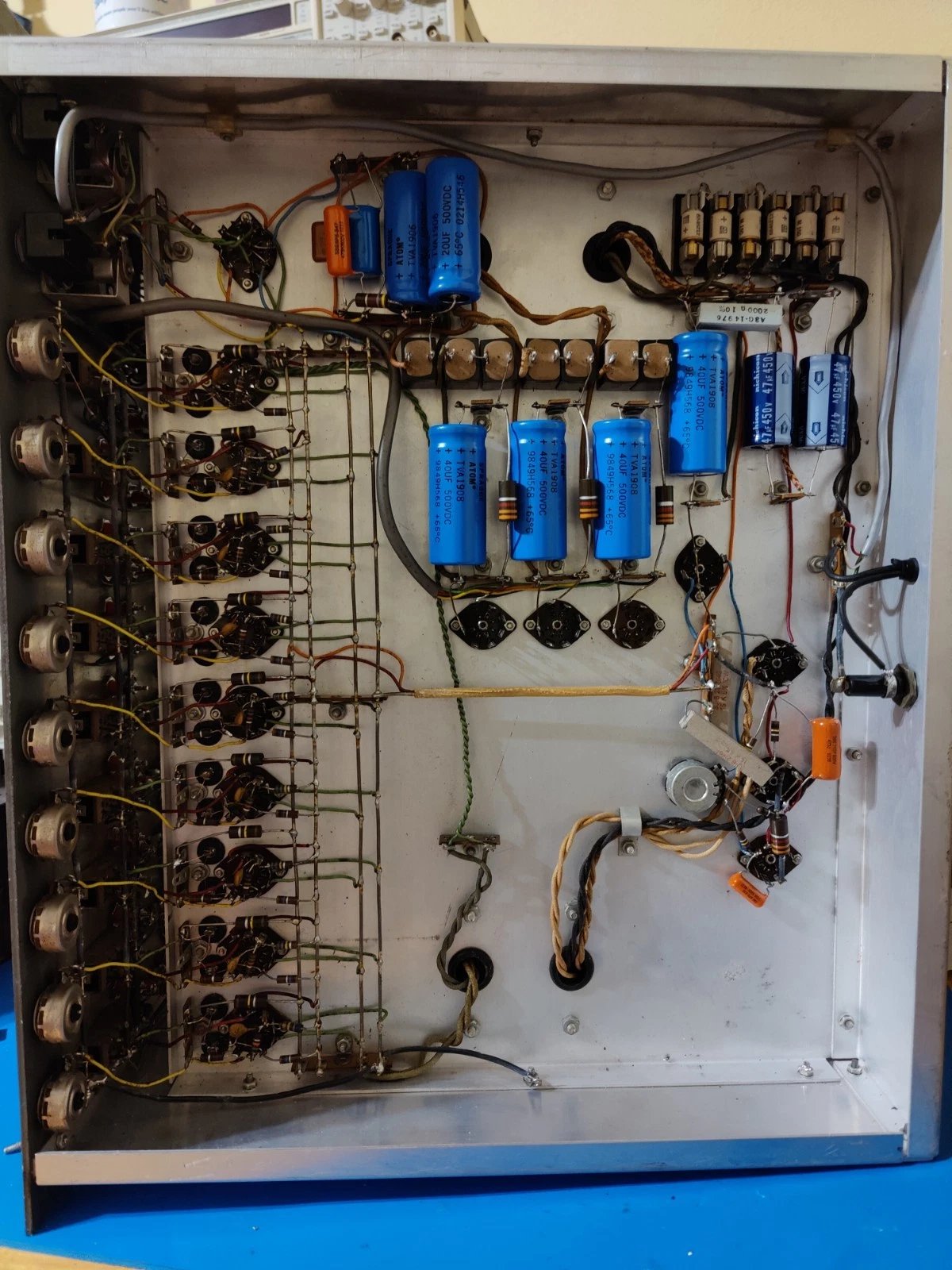
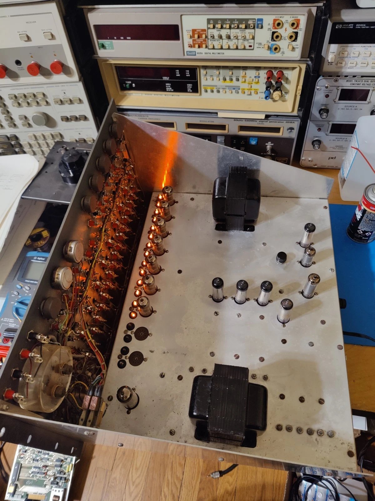
2.11.1 Chassis Interior — Running Condition
The photograph above shows the interior of a restored, operating EC-1. The nine 6U8 tube envelopes are visible in a row across the top of the chassis. The OA2/OB2 VR tubes — when illuminated — glow with characteristic purple-blue light through the chassis ventilation slots. The large cylindrical components to the left are the main HV filter capacitors and transformer.
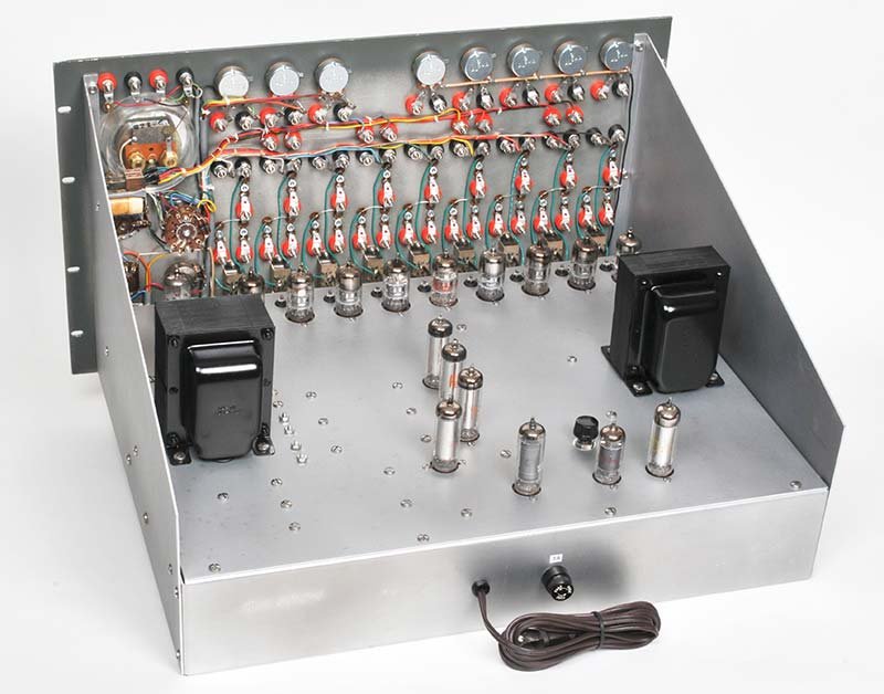
2.11.2 Chassis Interior — After Restoration
2.11.3 Resistor and Capacitor Problem-Element Plugs
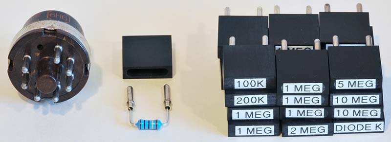
The two-pin plug-in format is unique to the EC-1. Each plug consists of a molded plastic (or machined Delrin) body with two brass pins spaced to fit the front-panel sockets. The resistor or capacitor is soldered between the pin ends and the component body sits in the plug body. Plug bodies hold the component physically and route its electrical connections to the socket contacts.
2.12 Supplementary SVG Diagrams
2.12.1 Power Supply Regulation Tree
2.12.2 Single Operational Amplifier — Functional Signal Flow
2.12.3 Amplifier Mode Selection — Decision Flowchart
Operator goal for this amplifier?
        │
        ├─── Negate (invert) a signal ────► Rf = Ri (e.g., 1MΩ / 1MΩ) → gain = -1
        │
        ├─── Multiply by constant > 1 ───► Rf > Ri (e.g., 10MΩ / 1MΩ) → gain = -10
        │                                   (keep ratio ≤ 100 to stay in accuracy spec)
        │
        ├─── Sum multiple signals ────────► Multiple Ri each to SJ, one Rf → weighted sum
        │
        ├─── Integrate with respect to t ► Cf = 1µF in feedback, Ri = 1MΩ → τ = 1 sec
        │                                   faster: Ri = 100kΩ → τ = 0.1 sec
        │
        ├─── Multiply by 0–1 coefficient ► Use front-panel coefficient pot upstream of Ri
        │                                   (pot × signal feeds amplifier input)
        │
        └─── Initial condition? ──────────► Connect IC supply to SJ via 100kΩ during RESET
                                            Capacitor Cf charges to IC voltage
                                            OPERATE releases cap; integration starts from IC
Heathkit EC-1 — Volume 2 — Hardware & Theory of Operation. Cross-reference: see Vol 1 for history and acquisition; Vol 3 for patch panel and computing elements; Vol 4 for acquisition, restoration, alignment, and fault-finding; Vol 5 for programming methodology; Vol 6 for sample programs.
Comments (0)